
Specifications
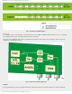

mikroElektronika | Free Online Book | PIC Microcontrollers | Chapter 3: I/O Ports
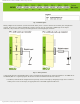
Fig. 3-8 IOCB register
Because of these features, the port B pins are commonly used for checking push-buttons on the keyboard because they
unerringly register any button press. Therefore, there is no need to “scan” these inputs all the time.
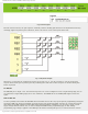
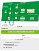
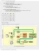
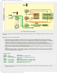
Fig. 3-9 Keyboard Example
When the X, Y and Z pins are configured as outputs set to logic one (1), it is only necessary to wait for an interrupt
request which arrives upon any button press. By combining zeros and units on these outputs it is checked which push-
button is pressed.
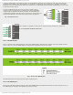
Pin RB0/INT
The RB0/INT pin is a single “true” external interrupt source. It can be configured to react to signal raising edge (zero-to-
one transition) or signal falling edge (one-to-zero transition). The INTEDG bit of the OPTION_REG register selects the
signal.
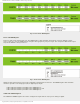
RB6 and RB7 Pins
You have probably noticed that the PIC16F887 microcontroller does not have any special pins for programming (writing the
program to ROM). The Ports pins available as general purpose I/O pins during normal operation are used for this purpose
(Port B pins clock (RB6) and data transfer (RB7) during program loading). In addition, it is necessary to apply a power
supply voltage Vdd (5V) and Vss (0V), as well as voltage for FLASH memory programming Vpp (12-14V). During
programming, Vpp voltage is applied to the MCLR pin. All details concerning this process, as well as which one of these
http://www.mikroe.com/en/books/picmcubook/ch3/ (6 of 10)5/3/2009 11:32:31 AM