
Specifications

mikroElektronika | Free Online Book | PIC Microcontrollers | Chapter 3: I/O Ports
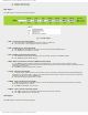
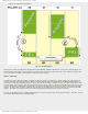
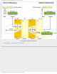
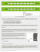
Fig. 3-2 Port A and TRISA Register
Similar to bits of the TRISA register which determine which of the pins will be configured as input and which as output,
the appropriate bits of the ANSEL register determine whether the pins will act as analog inputs or digital inputs/outputs.
● RA0 = AN0 (determined by bit ANS0 of the ANSEL register);
● RA1 = AN1 (determined by bit ANS1 of the ANSEL register);
● RA2 = AN2 (determined by bit ANS2 of the ANSEL register);
● RA3 = AN3 (determined by bit ANS3 of the ANSEL register); and
● RA5 = AN4 (determined by bit ANS4 of the ANSEL register).
Each bit of this port has an additional function related to some of built-in peripheral units. These additional functions will
be described in later chapters. This chapter covers only the RA0 pin’s additional function since it is related to Port A only.
ULPWU Unit
The microcontroller is commonly used in devices which have to operate periodically and, completely independently using
a battery power supply. In such cases, minimal power consumption is one of the priorities. Typical examples of such
applications are: thermometers, sensors for fire detection and similar. It is known that a reduction in clock frequency
reduces the power consumption, so one of the most convenient solutions to this problem is to slow the clock down (use
32KHz quartz crystal instead of 20MHz).
Setting the microcontroller to sleep mode is another step in the same direction.
However, even when both measures are applied, another problem arises. How to
wake the microcontroller and set it to normal mode. It is obviously necessary to
have an external signal to change logic state on some of the pins. Thus, the
problem still exists. This signal must be generated by additional electronics, which
causes higher power consumption of the entire device.
The ideal solution would be the microcontroller wakes up periodically by itself,
which is not impossible at all. The circuit which enables that is shown in figure on
the right.
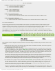
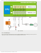
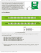
Fig. 3-3 ULPWU Unit
The principle of operation is simple:
A pin is configured as output and logic one (1) is brought to it. That causes the capacitor to be charged. Immediately after
this, the same pin is configured as an input. The change of logic state enables an interrupt and the microcontroller is set
to Sleep mode. Afterwards, there is nothing else to be done except wait for the capacitor to discharge by the leakage
current flowing out through the input pin. When it occurs, an interrupt takes place and the microcontroller continues with
the program execution in normal mode. The whole sequence is repeated...
http://www.mikroe.com/en/books/picmcubook/ch3/ (3 of 10)5/3/2009 11:32:31 AM