
Specifications

mikroElektronika | Free Online Book | PIC Microcontrollers | Chapter 2: Core SFRs
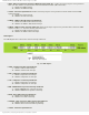
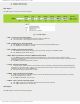
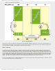
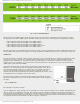
Fig. 2-15 PCON register
● ULPWUE - Ultra Low-Power Wake-up Enable bit
❍ 1 - Ultra Low-Power Wake-up enabled.
❍ 0 - Ultra Low-Power Wake-up disabled.
● SBOREN - Software BOR Enable bit
❍ 1 - Brown-out Reset enabled.
❍ 0 - Brown-out Reset disabled.
● POR - Power-on Reset Status bit
❍ 1 - No Power-on reset has occurred.
❍ 0 - Power-on reset has occurred. This bit must be set in software after a Power-on Reset occurs.
● BOR - Brown-out Reset Status bit
❍ 1 - No Brown-out reset has occurred.
❍ 0 - Brown-out reset has occurred. This bit must be set in software after a Brown-out Reset occurs.
PCL and PCLATH Registers
The size of the program memory of the PIC16F887 is 8K. Therefore, it has 8192 locations for program storing. For this
reason the program counter must be 13-bits wide (2^13 = 8192). In order that the contents of some location may be
changed in software during operation, its address must be accessible through some SFR. Since all SFRs are 8-bits wide, this
register is “artificially” created by dividing its 13 bits into two independent registers: PCLATH and PCL.
If the program execution does not affect the program counter, the value of this register is automatically and constantly
incremented +1, +1, +1, +1... In that way, the program is executed just as it is written- instruction by instruction, followed
by a constant address increment.
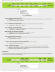
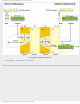
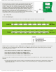
Fig. 2-16 PCL and PCLATH Registers
If the program counter is changed in software, then there are several things that should be kept in mind in order to avoid
problems:
● Eight lower bits (the low byte) come from the PCL register which is readable and writable, whereas five upper bits
coming from the PCLATH register are writable only.
● The PCLATH register is cleared on any reset.
● In assembly language, the value of the program counter is marked with PCL, but it obviously refers to 8 lower bits
only. One should take care when using the “ADDWF PCL” instruction. This is a jump instruction which specifies the
target location by adding some number to the current address. It is often used when jumping into a look-up table or
program branch table to read them. A problem arises if the current address is such that addition causes change on
some bit belonging to the higher byte of the PCLATH register. Do you see what is going on?
Executing any instruction upon the PCL register simultaneously causes the Prog ram Counter bits to be replaced by
the contents of the PCLATH register. However, the PCL register has access to only 8 lower bits of the instruction
result and the following jump will be completely incorrect. The problem is solved by setting such instructions at
addresses ending by xx00h. This enables the program to jump up to 255 locations. If longer jumps are executed by
this instruction, the PCLATH register must be incremented by 1 for each PCL register overflow.
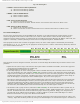
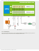
● On subroutine call or jump execution (instructions CALL and GOTO), the microcontroller is able to provide only 11-
bit addressing. For this reason, similar to RAM which is divided in “banks”, ROM is divided in four “pages” in size of
2K each. Such instructions are executed within these pages without any problems. Simply, since the processor is
provided with 11-bit address from the program, it is able to address any location within 2KB. Figure 2-17 below
illustrates this situation as a jump to the subroutine PP1 address.
However, if a subroutine or jump address are not within the same page as the location from where the jump is, two
“missing”- higher bits should be provided by writing to the PCLATH register. It is illustrated in figure 2-17 below as a
http://www.mikroe.com/en/books/picmcubook/ch2/ (10 of 12)5/3/2009 11:32:08 AM