
Specifications

mikroElektronika | Free Online Book | PIC Microcontrollers | Chapter 2: Core SFRs
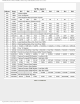
1 1 0 1:128 1:64
1 1 1 1:256 1:128
Table 2-2
In order to achieve 1:1 prescaler rate when the timer TMR0 counts up pulses, the prescaler should be assigned to the WDT.
As a result of this, the timer TMR0 does not use the prescaler, but directly counts pulses generated by the oscillator, which
was the objective!
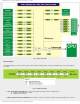
Interrupt System Registers
When an interrupt request arrives it does not mean that interrupt will automatically occur, because it must also be
enabled by the user (from within the program). Because of that, there are special bits used to enable or disable interrupts.
It is easy to recognize these bits by IE contained in their names (stands for Interrupt Enable). Besides, each interrupt is
associated with another bit called the flag which indicates that interrupt request has arrived regardless of whether it is
enabled or not. They are also easily recognizable by the last two letters contained in their names- IF (Interrupt Flag).
As seen, everything is based on a simple and efficient idea. When an interrupt request arrives, the flag bit is to be set first.
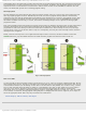
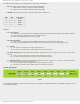
Fig. 2-8 Interrupt System Registers
If the appropriate IE bit is not set (0), this event will be completely ignored. Otherwise, an interrupt occurs! In case
several interrupt sources are enabled, it is necessary to detect the active one before the interrupt routine starts
execution. Source detection is performed by checking flag bits.
It is important to understand that the flag bits are not automatically cleared, but by software during interrupt routine
execution. If this detail is neglected, another interrupt will occur immediately upon return to the program, even though
there are no more requests for its execution! Simply put, the flag as well as IE bit remained set.
All interrupt sources typical of the PIC16F887 microcontroller are shown on the next page. Note several things:
● GIE bit - enables all unmasked interrupts and disables all interrupts simultaneously.
● PEIE bit - enables all unmasked peripheral interrupts and disables all peripheral interrupts (This does not concern
Timer TMR0 and port B interrupt sources).
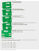
To enable interrupt caused by changing logic state on port B, it is necessary to enable it for each bit separately. In this
case, bits of the IOCB register have the function to control IE bits.
http://www.mikroe.com/en/books/picmcubook/ch2/ (4 of 12)5/3/2009 11:32:08 AM