
Specifications

mikroElektronika | Free Online Book | PIC Microcontrollers | Chapter 2: Core SFRs
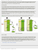
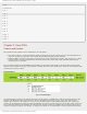
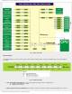
● RBPU - Port B Pull up Enable bit.
❍ 1 - PortB pull-ups are disabled.
❍ 0 - PortB pull-ups are enabled.
Fig.2-3
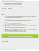
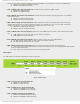
● INTEDG - Interrupt Edge Select bit.
❍ 1 - Interrupt on rising edge of RB0/INT pin.
❍ 0 - Interrupt on falling edge of RB0/INT pin.
Fig.2-4
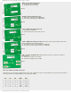
● T0CS - TMR0 Clock Source Select bit.
❍ 1 - Transition on TOCKI pin.
❍ 0 - Internal instruction cycle clock (Fosc/4).
Fig.2-5
● T0SE - TMR0 Source Edge Select bit selects pulse edge (rising or falling) counted by
the timer TMR0 through the RA4/T0CKI pin.
❍ 1 - Increment on high-to-low transition on TOCKI pin.
❍ 0 - Increment on low-to-high transition on TOCKI pin.
Fig.2-6
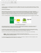
● PSA - Prescaler Assignment bit assigns prescaler (only one exists) to the timer or
watchdog timer.
❍ 1 - Prescaler is assigned to the WDT.
❍ 0 - Prescaler is assigned to the TMR0.
Fig.2-7
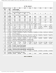
PS2, PS1, PS0 Prescaler Rate Select bits
Prescaler rate is selected by combining these three bits. Described, as shown in the table below, prescaler rate depends on
whether prescaler is assigned (TMR0) or watch-dog timer (WDT).
PS2 PS1 PS0 TMR0 WDT
0 0 0 1:2 1:1
0 0 1 1:4 1:2
0 1 0 1:8 1:4
0 1 1 1:16 1:8
1 0 1 1:64 1:32
http://www.mikroe.com/en/books/picmcubook/ch2/ (3 of 12)5/3/2009 11:32:08 AM