
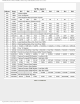
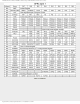
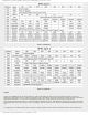
Specifications

mikroElektronika | Free Online Book | PIC Microcontrollers | Chapter 2: Core SFRs
not affect any Status bits (C, DC and Z). Refer to “Instruction Set Summary”.
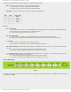
● IRP - Bit selects register bank. It is used for indirect addressing.
❍ 1 - Banks 0 and 1 are active (memory location 00h-FFh)
❍ 0 - Banks 2 and 3 are active (memory location 100h-1FFh)
● RP1,RP0 - Bits select register bank. They are used for direct addressing.
RP1 RP0 Active Bank
0 0 Bank0
0 1 Bank1
1 0 Bank2
1 1 Bank3
Table 2-1
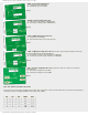
● TO - Time-out bit.
❍ 1 - After power-on or after executing CLRWDT instruction which resets watch-dog timer or SLEEP instruction
which sets the microcontroller into low-consumption mode.
❍ 0 - After watch-dog timer time-out has occurred.
● PD - Power-down bit.
❍ 1 - After power-on or after executing CLRWDT instruction which resets watch-dog timer.
❍ 0 - After executing SLEEP instruction which sets the microcontroller into low-consumption mode.
● Z - Zero bit
❍ 1 - The result of an arithmetic or logic operation is zero.
❍ 0 - The result of an arithmetic or logic operation is different from zero.
● DC - Digit carry/borrow bit is changed during addition and subtraction if an “overflow” or a “borrow” of the result
occurs.
❍ 1 - A carry-out from the 4th low-order bit of the result has occurred.
❍ 0 - No carry-out from the 4th low-order bit of the result has occurred.
● C - Carry/Borrow bit is changed during addition and subtraction if an “overflow” or a “borrow” of the result occurs,
i.e. if the result is greater than 255 or less than 0.
❍ 1 - A carry-out from the most significant bit of the result has occurred.
❍ 0 - No carry-out from the most significant bit of the result has occurred.
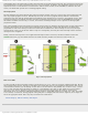
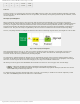
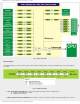
OPTION_REG Register
Fig.2-2
The OPTION_REG register contains various control bits to configure: Timer0/WDT prescaler, timer TMR0, external interrupt
and pull-ups on PORTB.
http://www.mikroe.com/en/books/picmcubook/ch2/ (2 of 12)5/3/2009 11:32:08 AM