
Specifications

mikroElektronika | Free Online Book | PIC Microcontrollers | Appendix B: Examples
movf PCLATH ; Save register PCLATH
movwf pclath_temp
banksel CCPR1L
btfss DARK ; Tests push-button "DARK"
decf CCPR1L ; Push-button is pressed - decrement CCP1L by 1
btfss BRIGHT ; Testing push-button "BRIGHT"
incf CCPR1L ; Push-button is pressed - increment CCP1L by 1
movf pclath_temp,w ; PCLATH is given its original content
movwf PCLATH
movf status_temp,w ; STATUS is given its original content
movwf STATUS
swapf w_temp,f ; W is given its original content
swapf w_temp,w
banksel PIR1 ; Selects bank containing PIR1
bcf PIR1,TMR1IF ; Clears interrupt flag TMR1IF
bsf TMR1H,7 ; Accelerates timer TMR0 counting
bsf TMR1H,6 ;
bsf INTCON,GIE ; Global interrupt enabled
retfie ; Return from interrupt routine
;************************ MAIN PROGRAM **************************************
main ; Start of the main program
banksel ANSEL ; Selects bank containing register ANSEL
clrf ANSEL ; Clears registers ANSEL and ANSELH
clrf ANSELH ; All pins are digital
banksel OPTION_REG ; Selects bank containing register ANSEL
bcf OPTION_REG,7 ; Pull-up resistors enabled
bsf WPUB,0 ; Pull-up resistors enabled
bsf WPUB,1 ; on port B pins 0 and 1
banksel TRISC ; Selects bank containing register TRISC
clrf TRISC ; All port C pins are configured as outputs
banksel T1CON ; Selects bank containing register T1CON
bcf T1CON,TMR1CS ; TMR1 operates as a timer
bcf T1CON,T1CKPS0 ; Prescaler rate is 1:8
bcf T1CON,T1CKPS1
bsf T1CON,TMR1ON ; Activates timer TMR1
banksel PIE1 ; Selects bank containing register PIE1
bsf PIE1,TMR1IE ; Interrupt TMR1 is enabled
bsf INTCON,PEIE ; Peripheral modules interrupts are
; enabled
bsf INTCON,GIE ; Global interrupt enabled
movlw B'11111101' ; Prescaler TMR2 = 1:4
banksel T2CON
movwf T2CON
movlw B'11111111' ; Number in register PR2
banksel PR2
movwf PR2
banksel CCP1CON
movlw B'00001100' ; Bits to configure CCP1 module
movwf CCP1CON
loop
goto loop ; Remain here
end ; End of program
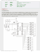
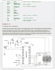
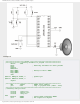
EXAMPLE 11
Using A/D converter
PIC16F887 A/D converter is used in this example. Everything is quite simple. A variable analog signal is applied on the AN2
pin while the result of conversion is shown on port B as a binary number. In order to simplify the program as much as
http://www.mikroe.com/en/books/picmcubook/appb/ (37 of 54)5/3/2009 11:36:02 AM