
Specifications

mikroElektronika | Free Online Book | PIC Microcontrollers | Appendix B: Examples
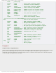
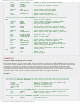
movwf w_temp ; Save register W
movf STATUS ; Save register STATUS
movwf status_temp
movf PCLATH ; Save register PCLATH
movwf pclath_temp
banksel PORTB ; Selects bank containing PORTB
incf PORTB ; Increments PORTB register by 1
banksel PR2 ; Selects bank containing PR2
decf PR2 ; PR2 is decremented by 1
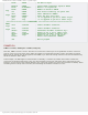
movf pclath_temp,w ; PCLATH is given its original state
movwf PCLATH
movf status_temp,w ; STATUS is given its original state
movwf STATUS
swapf w_temp,f ; W is given its original state
swapf w_temp,w
banksel PIR1 ; Selects bank containing PIR1
bcf PIR1,TMR2IF ; Clears interrupt flag TMR2IF
bsf INTCON,GIE ; Global interrupt enabled
retfie ; Return from interrupt routine
;************************ MAIN PROGRAM *******************************************
main ; Start of the main program
banksel OSCCON ; Selects bank containing register OSCCON
bcf OSCCON,6 ; Selects internal oscillator HFINTOSC with
bsf OSCCON,5 ; frequency of 500KHz
bsf OSCCON,4
bsf OSCCON,0 ; Microcontroller uses internal oscillator
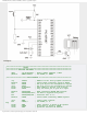
banksel ANSEL ; Selects bank containing register ANSEL
clrf ANSEL ; Clears registers ANSEL and ANSELH
clrf ANSELH ; All pins are digital
banksel TRISB ; Selects bank containing register TRISB
clrf TRISB ; All port B pins are configured as outputs
clrf PR2
banksel T2CON ; Selects bank containing register T2CON
movlw H'FF' ; Sets all control register bits
movwf T2CON ; prescaler=1:16, postscaler=1:16 TMR2=ON
clrf PORTB
banksel PIE1 ; Selects bank containing register PIE1
bsf PIE1,TMR2IE ; TMR2 interrupt enabled
bsf NTCON,PEIE ; Peripheral modules interrupt enabled
; Timer TMR2 belongs to peripheral modules
bsf INTCON,GIE ; Global interrupt enabled
loop
goto loop ; Remain here
end ; End of program
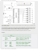
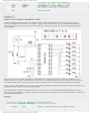
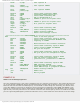
EXAMPLE 10
Module CCP1 as PWM signal generator
Since the CCP modules have a wide range of possibilities they are commonly used in practice. This example illustrates the
use of CCP1 module in PWM mode. Bits of the CCP1CON register determine that the module operates as a single-output
PWM. The same bits determine the PWM frequency to be 4.88 kHz. To make things more interesting, the duration of the
output P1A (PORTC,2) pulses may be changed by means of push-buttons symbolically called "DARK" and "BRIGHT". Push-
buttons are tested in interrupt routine initiated by the timer TMR1. Any change affects the LED diode so that it changes
light intensity. Note that port B does not use external resistors because internal pull-up resistors are enabled. The whole
process of generating PWM signal is performed "behind the scenes", which enables the microcontroller to do other things.
http://www.mikroe.com/en/books/picmcubook/appb/ (35 of 54)5/3/2009 11:36:02 AM