
Specifications

mikroElektronika | Free Online Book | PIC Microcontrollers | Appendix B: Examples
EXAMPLE 2
Using program loop and internal oscillator LFINTOSC
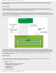
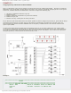
This is a continuation of the previous example, but deals with a bit more complicated problem... The idea is to make the
LED diodes on the port B blink. A simple thing at first glance! It is enough to periodically change logic state on the port B.
In this case, numbers 01010101 and 10101010 are selected to change in the following way:
1. Set binary combination 01010101 on port B;
2. Remain in loop1;
3. Replace existing bits combination on port B with 10101010;
4. Remain in loop2; and
5. Return to the step 1 and repeat the whole procedure.
Do you know how fast this should be done? It would be possible to observe changes on port B only if, apart from the delays
provided in loop1 and loop2, the whole process is slowed down approximately 250 times more. Because of this, the
microcontroller uses internal oscillator LFINTOSC with the frequency of 31kHz instead of the external oscillator with
quartz crystal (8MHz).
You have noticed that the clock signal source has changed "on the fly". If you want to make sure of it, remove quartz
crystal prior to switching the microcontroller on. What will happen? The microcontroller will not start operating because
the config word loaded with the program requires the use of the crystal on switching on. If you remove the crystal later
during the operation, it will not affect the microcontroller at all!
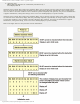
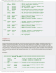
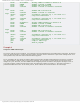
Example 2:
;************************************************************************
; Header
;************************************************************************
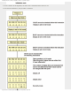
;************* DEFINING VARIABLES ***************************************
cblock 0x20 ; Block of variables starts at address 20h
counter1 ; Variable "counter1" at address 20h
endc
http://www.mikroe.com/en/books/picmcubook/appb/ (22 of 54)5/3/2009 11:36:02 AM