
Specifications

mikroElektronika | Free Online Book | PIC Microcontrollers | Appendix B: Examples
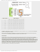
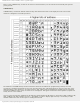
Control of operating
4 RS
0
1
D0 – D7 are interpreted as commands
D0 – D7 are interpreted as data
5 R/W
0
1
Write data (from controller to LCD)
Read data (from LCD to controller)
6 E
0
1
From 1 to 0
Access to LCD disabled
Normal operating
Data/commands are transferred to LCD
Data / commands
7 D0 0/1 Bit 0 LSB
8 D1 0/1 Bit 1
9 D2 0/1 Bit 2
10 D3 0/1 Bit 3
11 D4 0/1 Bit 4
12 D5 0/1 Bit 5
13 D6 0/1 Bit 6
14 D7 0/1 Bit 7 MSB
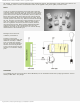
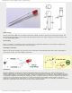
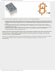
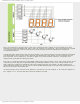
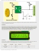
LCD screen
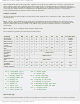
The LCD screen consists of two lines with 16 characters each. Every character consists of 5x8 or 5x11 dot matrix. This
book covers the 5x8 character display, which is indeed the most commonly used.
Display contrast depends on the power supply voltage and whether messages are displayed in one or two lines. For this
reason, varying voltage 0-Vdd is applied on the pin marked as Vee. Trimmer potentiometer is usually used for that
purpose. Some LCD displays have built in backlight (blue or green diodes). When used during operation, a current limiting
resistor should be serially connected to one of the pins for backlight (similar to LED diodes).
http://www.mikroe.com/en/books/picmcubook/appb/ (12 of 54)5/3/2009 11:36:02 AM