
Specifications

mikroElektronika | Free Online Book | PIC Microcontrollers | Appendix B: Examples
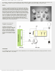
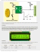
Here is an explanation on the figure above. First a byte representing units is applied on a microcontroller port and a
transistor T1 is activated simultaneously. After a while, the transistor T1 is turned off, a byte representing tens is applied
on a port and transistor T2 is activated. This process is being cyclically repeated at high speed for all digits and
corresponding transistors.
A disappointing fact which indicates that the microcontroller is just a kind of miniature computer designed to understand
only the language of zeros and ones is fully expressed when displaying any digit. Namely, the microcontroller does not
know what units, tens or hundreds are, nor what ten digits we are used to look like. Therefore, each number to be
displayed must go through the following procedure:
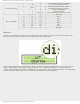
First of all, in a particular subroutine a multi-digital number must be split into units, tens etc. Then, these must be stored
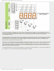
in special bytes each. Digits get recognizable format by performing "masking". In other words, a binary format of each
digit is replaced by a different combination of bits using a simple subroutine. For example, the digit 8 (0000 1000) is
replaced by binary number 0111 1111 in order to activate all LEDs displaying digit 8. The only diode remaining inactive in
this case is reserved for the decimal point.
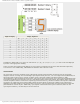
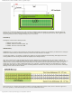
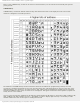
If a microcontroller port is connected to the display in a way that bit 0 activates segment "a", bit 1 activates segment "b",
bit 2 segment "c" etc., then the table below shows the mask for each digit.
http://www.mikroe.com/en/books/picmcubook/appb/ (9 of 54)5/3/2009 11:36:02 AM