
Specifications

mikroElektronika | Free Online Book | PIC Microcontrollers | Appendix B: Examples
Clearly, it is about simple circuits, but it does not have to always be like that. If the target device is used for controlling
expensive machines or maintaining vital functions, everything gets more and more complicated! However, this solution is
sufficient for the time being...
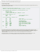
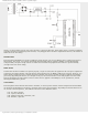
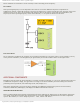
POWER SUPPLY
Even though the PIC16F887 can operate at different supply voltages, why to test "Murphy's low"?! A 5DC power supply is
shown above. The circuit, uses a cheap integrated three-terminal positive regulator, LM7805, provides high-quality
voltage stability and quite enough current to enable microcontroller and peripheral electronics to operate normally
(enough in this case means 1Amp).
RESET SIGNAL
In order that the microcontroller can operate properly, a logic one (VCC) must be applied on the reset pin it explains the
connection pin-resistor 10K-VCC. The push-button connecting the reset pin MCLR to GND is not necessary. However, it is
almost always provided because it enables the microcontroller safe return to normal operating conditions if something
goes wrong. By pushing this button, 0V is brought to the pin, the microcontroller is reset and program execution starts
from the beginning. The 10K resistor is there to allow 0V to be applied to the MCLR pin, via the push-button, without
shorting the 5VDC rail to ground.
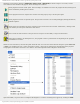
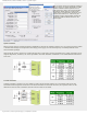
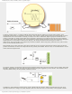
CLOCK SIGNAL
Even though the microcontroller has a built in oscillator, it cannot operate without external components which stabilize
its operation and determine its frequency (operating speed of the microcontroller). Depending on which elements are in
use as well as their frequencies, the oscillator can be run in four different modes:
● LP - Low Power Crystal;
● XT - Crystal / Resonator;
● HS - High speed Crystal / Resonator; and
● RC - Resistor / Capacitor.
http://www.mikroe.com/en/books/picmcubook/appb/ (2 of 54)5/3/2009 11:36:02 AM