
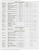
Specifications


mikroElektronika | Free Online Book | PIC Microcontrollers | Chapter 9: Instruction Set
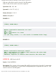
The PIC16F887 executes instructions GOTO, CALL, RETURN in the same way as all other
microcontrollers do. A difference is that stack is independent from internal RAM and has 8
levels. The ‘RETLW k’ instruction is identical to RETURN instruction, with exception that a
constant defined by instruction operand is written to the W register prior to return from
subroutine. This instruction enables Lookup tables to be easily created by creating a table
as a subroutine consisting of ‘RETLWk‘ instructions, where the literals ‘k’ belong to the
table. The next step is to write the position of the literals k (0, 1, 2, 3...n) to W register and
call the subroutine (table) using the CALL instruction. Table below consists of the following
literals: k0, k1, k2...kn.
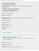
Main movlw 2 ;write number 2 to accumulator
call Lookup ;jump to the lookup table
Lookup addwf PCL,f ;add accumulator and program cur
;rent address (PCL)
retlw k0 ;return from subroutine (accumulator contains
k0)
retlw k1 ;...
retlw k2 ;...
... ;...
... ;...
retlw kn ;return from subroutine (accumulator contains
kn)
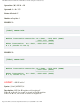
The first line of the subroutine ( instruction ADDWF PCL,f )simply adds a literal "k" from W
register and table start address which is stored in the PCL register. The result is real data
address in program memory. Upon return from the subroutine, the W register will contain
the addressed literal k. In this case, it is the "k2" literal.
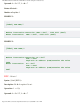
RETFIE (RETurn From IntErrupt) represents a return from interrupt routine. In contrast to
the RETURN instruction, it may automatically set the GIE bit (Global Interrupt Enable).
When an interrupt occurs this bit is automatically cleared. Only the program counter is
pushed to the stack, which means that there is no auto save of registers’ status and the
current status either. The problem is solved by saving status of all important registers at the
beginning of interrupt routine. These values are retrieved to these registers immediately
before leaving the interrupt routine.
Conditional jumps are executed by two instructions: BTFSC and BTFSS. Depending on the
state of bit being tested in the ‘f’ register, the following instruction will be skipped or not.
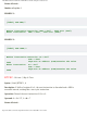
Instruction Execution Time
All instructions are single-cycle instructions. The only exception may be conditional branch
instructions (if condition is met) or instructions being executed upon the program counter.
In both cases, two cycles are required for instruction execution where the second cycle is
executed as a NOP (No Operation). A single-cycle instruction consists of four clock cycles. If
4MHz oscillator is used, a nominal time for instruction execution is 1μS. In case of jump,
the instruction execution time is 2μS.
Legend
http://www.mikroe.com/en/books/picmcubook/ch9/ (4 of 35)5/3/2009 11:35:12 AM