
Specifications


mikroElektronika | Free Online Book | PIC Microcontrollers | Chapter 9: Instruction Set
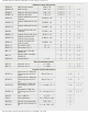
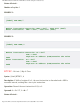
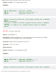
RETFIE Return from interrupt TOS -> PC, 1 -> GIE 2
Other instructions
NOP No operation TOS -> PC, 1 -> GIE 1
CLRWDT Clear watchdog timer
0 -> WDT, 1 -> TO, 1
-> PD
TO, PD 1
SLEEP Go into sleep mode
0 -> WDT, 1 -> TO, 0
-> PD
TO, PD 1
Table 9-1 16Fxx Instruction Set
*1 When an I/O register is modified as a function of itself, the value used will be that value
present on the pins themselves.
*2 If the instruction is executed on the TMR register and if d=1, the prescaler will be cleared.
*3 If the PC is modified or test result is logic one (1), the instruction requires two cycles.
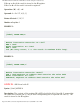
Data Transfer Instructions
Data Transfer within the microcontroller takes place between working register W (called
accumulator) and a register which represents any location of internal RAM regardless of
whether it is about special function or general purpose registers.
First three instructions move literal to W register (MOVLW stands for move Literal to W),
move data from W register to RAM and from RAM to W register (or to the same RAM location
with change on flag Z only). Instruction CLRF clears f register, whereas CLRW clears W
register. SWAPF instruction swaps nibbles within f register (one nibble contains four bits).
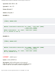
Arithmetic-logic Instructions
Similar to most microcontrollers, PIC supports only two arithmetic instructions- addition and
subtraction. Flags C, DC, Z are automatically set depending on the results of addition or
subtraction. The only exception is the flag C. Since subtraction is performed as addition with
negative value, the flag C is inverted after subtraction. It means that the flag C is set if it is
possible to perform operation and cleared if the larger number is subtracted from smaller
one. Logic one (1) of the PIC is able to perform operations AND, OR, EX-OR, inverting (COMF)
and rotation (RLF and RRF).
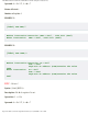
Instructions which rotate a register actually rotate its bits through the flag C by one bit left
(toward bit 7) or right (toward bit 0). The bit shifted from the register is moved to the flag C
which is automatically moved to the bit on the opposite side of the register.
Bit-oriented Instructions
Instructions BCF and BSF clear or set any bit in memory. Although it seems to be a simple
operation, it is not like that. CPU first reads the entire byte, changes one its bit and
rewrites the whole byte to the same location.
Program Control Instructions
http://www.mikroe.com/en/books/picmcubook/ch9/ (3 of 35)5/3/2009 11:35:12 AM