
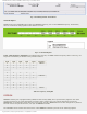
Specifications

mikroElektronika | Free Online Book | PIC Microcontrollers | Chapter 8: Other MCU's Circuits
In order to read data EEPROM memory, follow the procedure below:
Step 1: Write an address (00h - FFh) to the EEADR register;
Step 2: Select EEPROM memory block by clearing the EEPGD bit of the EECON1 register;
Step 3: To read location, set the RD bit of the same register; and
Step 4: Data is stored in the EEDAT register and ready to use.
The following example illustrates data EEPROM read:
BSF STATUS,RP1 ;
BCF STATUS,RP0 ; Access bank 2
MOVF ADDRESS,W ; Move address to the W register
MOVWF EEADR ; Write address
BSF STATUS,RP0 ; Access bank 3
BCF EECON1,EEPGD ; Select EEPROM
BSF EECON1,RD ; Read data
BCF STATUS,RP0 ; Access bank 2
MOVF EEDATA,W ; Data is stored in the W register
Write to Data EEPROM Memory
In order to write data to EEPROM memory, first it is necessary to write the address to the EEADR register first and data to
the EEDAT register afterwards. Then you have to follow a special sequence to initiate write for each byte. Interrupts must
be disabled during this procedure.
Data EEPROM write is illustrated in the example below:
BSF STATUS,RP1
BSF STATUS,RP0
BTFSC EECON,WR1 ; Wait for the previous write to complete
GOTO $-1 ;
BCF STATUS,RP0 ; Bank 2
MOVF ADDRESS,W ; Move address to W
MOVWF EEADR ; Write address
MOVF DATA,W ; Move data to W
MOVWF EEDATA ; Write data
BSF STATUS,RP0 ; Bank 3
BCF EECON1,EEPGD ; Select EEPROM
BSF EECON1,WREN ; Write to EEPROM enabled
BCF INCON,GIE ; All interrupts disabled
MOVLW 55h ; Required sequence start
MOVWF EECON2
MOVLW AAh
MOVWF EECON2 ; Required sequence end
BSF EECON1,WR
BSF INTCON,GIE ; Interrupts enabled
BCF EECON1,WREN ; Write to EEPROM disabled
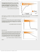
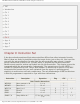
Reset! Black-out, Brown-out or Noises?
On reset, the microcontroller immediately stops operation and clears its registers. Reset signal may be generated
externally at any moment (low logic level on the MCLR pin). If needed it can be also generated by internal control logic.
Power-on always causes reset. Namely, because of many transitional events which take place when power supply is on
( switch contact flashing and sparkling, slow voltage rise, gradual clock frequency stabilization etc.), it is necessary to
provide a certain time delay before the microcontroller starts operating. Two internal timers- PWRT and OST are in charge
of that. The first one can be enabled or disabled during program writing. The scenario is as follows:
http://www.mikroe.com/en/books/picmcubook/ch8/ (13 of 15)5/3/2009 11:34:45 AM