
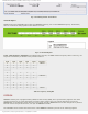
Specifications

mikroElektronika | Free Online Book | PIC Microcontrollers | Chapter 8: Other MCU's Circuits
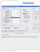
Similar to the external oscillator, the internal one can also operate in several modes. The mode is selected in the same
way as in case of external oscillator- using bits of the Config Word register. In other words, everything is performed within
PC software, immediately before program writing to the microcontroller starts.
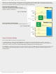
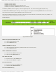
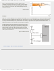
Internal oscillator in INTOSC mode
In this mode, the OSC1 pin is available as general
purpose I/O while the OSC2 pin outputs selected internal
oscillator frequency divided by 4.
Fig. 8-11 INTOSC Mode
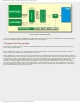
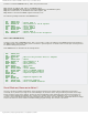
Internal oscillator in INTOSCIO mode
In this mode, both pins are available for general purpose I/O.
Fig. 8-12 INTOSCIO Mode
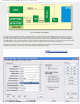
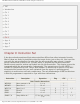
Internal Oscillator Settings
The internal oscillator consists of two separate circuits.
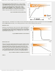
1. The high-frequency internal oscillator HFINTOSC is connected to the postscaler (frequency divider). It is factory
calibrated and operates at 8MHz. Using postscaler, this oscillator can output clock sources at one of seven frequencies
which can be selected via software using the IRCF2, IRCF1 and IRCF0 pins of the OSCCON register.
The HFINTOSC is enabled by selecting one of seven frequencies (between 8 MHz and 125 kHz) and setting the System Clock
Source (SCS) bit of the OSCCON register afterwards. As seen in figure below, everything is performed using bits of the
OSCCON register.
http://www.mikroe.com/en/books/picmcubook/ch8/ (7 of 15)5/3/2009 11:34:45 AM