
Specifications

mikroElektronika | Free Online Book | PIC Microcontrollers | Chapter 7: Analog Modules
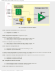
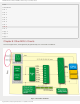
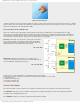
Fig. 7-13 VRCON Register
VREN Comparator C1 Voltage Reference Enable bit
● 1 - Voltage reference CVref source is powered on; and
● 0 - Voltage reference CVref source is powered off.
VROE Comparator C2 Voltage Reference Enable bit
● 1 - Voltage reference CVref is connected to the pin; and
● 0 - Voltage reference CVref is disconnected from the pin.
VRR - CVref Range Selection bit
● 1 - Voltage reference source is set to low range; and
● 0 - Voltage reference source is set to high range.
VRSS - Comparator Vref Range selection bit
● 1 - Voltage reference source is in the range of Vref+ to Vref-; and
● 0 - Voltage reference source is in the range of Vdd - Vss (power supply voltage).
VR3 - VR0 CVref Value Selection
If VRR = 1 (low range)
Voltage reference is calculated using the formula: CVref = ([VR3:VR0]/24)Vdd
If VRR = 0 (high range)
Voltage reference is calculated using the formula: CVref = Vdd/4 + ([VR3:VR0]/32)Vdd
In Short:
In order to properly use built in Comparators, it is necessary to do the following:
Step 1 - Configuring module:
● In order to select the appropriate mode, bits of the registers CM1CON0 and CM2CON0 should be configured.
Interrupt should be disabled on any change of mode.
Step 2 - Configuring internal voltage reference Vref source (only when used). In the VRCON register it is necessary to :
● Select one of two voltage ranges using the VRR bit;
● Configure necessary Vref using bits VR3 - VR0;
● Set the VROE bit if needed; and
● Enable voltage Vref source by setting the VREN bit.
http://www.mikroe.com/en/books/picmcubook/ch7/ (13 of 14)5/3/2009 11:34:24 AM