
Specifications

mikroElektronika | Free Online Book | PIC Microcontrollers | Chapter 7: Analog Modules
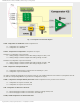
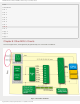
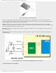
Fig. 7-11 Comparator C2 Schematic Diagram
C2ON - Comparator C2 Enable bit enables comparator C2.
● 1 - Comparator C2 is enabled; and
● 0 - Comparator C2 is disabled.
C2OUT - Comparator C2 Output bit is comparator C2 output.
If C2POL = 1 (comparator output inverted)
● 1 - Analog voltage at C1Vin+ is lower than analog voltage at C1Vin-; and
● 0 - Analog voltage at C1Vin+ is higher than analog voltage at C1Vin-.
If C2POL = 0 (comparator output non-inverted)
● 1 - Analog voltage at C1Vin+ is higher than analog voltage at C1Vin-; and
● 0 - Analog voltage at C1Vin+ is lower than analog voltage at C1Vin-.
C2OE - Comparator C2Output Enable bit
● 1 - Comparator C2OUT output is connected to the C2OUT pin.*; and
● 0 - Comparator output is internal only.
* In order to enable the C2OUT bit to be present on the pin, two conditions must be met: C2ON = 1 (comparator must be
on) and the corresponding TRIS bit = 0 (pin must be configured as output).
C2POL - Comparator C2 Output Polarity Select bit enables comparator C2 out put state to be inverted.
● 1 - Comparator C2 output is inverted; and
● 0 - Comparator C2 output is non-inverted.
C2R - Comparator C2 Reference Select bit
● 1 - Non-inverting input C2Vin+ is connected to reference voltage C2Vref; and
● 0 - Non-inverting input C2Vin+ is connected to the C2IN+ pin.
C2CH1, C2CH0 Comparator C2 Channel Select bit
http://www.mikroe.com/en/books/picmcubook/ch7/ (11 of 14)5/3/2009 11:34:24 AM