
Specifications

mikroElektronika | Free Online Book | PIC Microcontrollers | Chapter 7: Analog Modules
● 1 - Comparator C1OUT output is connected to the C1OUT pin.*; and
● 0 - Comparator output is internal only.
* In order to enable the C1OUT bit to be present on the pin, two conditions must be met: C1ON = 1 (comparator must be
on) and the corresponding TRIS bit = 0 (pin must be configured as output).
C1POL - Comparator C1 Output Polarity Select bit enables comparator C1 out put state to be inverted.
● 1 - Comparator C1 output is inverted; and
● 0 - Comparator C1 output is non-inverted.
C1R - Comparator C1 Reference Select bit
● 1 - Non-inverting input C1Vin+ is connected to reference voltage C1Vref; and
● 0 - Non-inverting input C1Vin+ is connected to the C1IN+ pin.
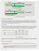
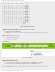
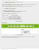
C1CH1, C1CH0 - Comparator C1 Channel Select bit
C1CH1 C1CH0 Comparator C1Vin- input
0 0 Input C1Vin- is connected to the C12IN0- pin
0 1 Input C1Vin- is connected to the C12IN1- pin
1 0 Input C1Vin- is connected to the C12IN2- pin
1 1 Input C1Vin- is connected to the C12IN3- pin
Table 7-4 Comparator C1
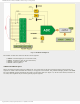
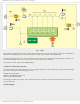
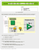
CM2CON0 Register
Fig. 7-10 CM2CON0 Regsiter
Bits of this register are in control of comparator C2. Similar to the previous case, the figure 7-11 shows a simplified
schematic of the circuit affected by the bits of this register.
http://www.mikroe.com/en/books/picmcubook/ch7/ (10 of 14)5/3/2009 11:34:24 AM