
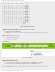
Specifications

mikroElektronika | Free Online Book | PIC Microcontrollers | Chapter 7: Analog Modules
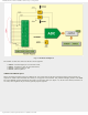
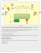
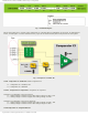
Fig. 7-7 VREF
The comparator voltage reference has 2 ranges with 16 voltage levels in each range. Range selection is controlled by the
VRR bit of the VRCON register. The selected voltage reference may be output to the RA2/AN2 pin.
Even though the main idea was to obtain varying voltage reference for the operation of analog modules, a simple A/D
converter is obtained in that way too. This converter is very useful in some situations.
It's operation is under control of the VRCON register.
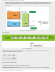
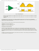
Comparators and Interrupt Operation
The flag bit CMIF of the register PIR is set on every change of logic state on any comparator's output. The same changes
also cause an interrupt if the following bits are set:
CMIE bit of the PIE register;
PEIE bit of the INTCON register; and
GIE bit of the INTCON register.
If interrupt is enabled, any change on the comparator's output can wake up the microcontroller from sleep mode if it is
setup in that mode.
CM1CON0 Register
http://www.mikroe.com/en/books/picmcubook/ch7/ (8 of 14)5/3/2009 11:34:24 AM