
Specifications

mikroElektronika | Free Online Book | PIC Microcontrollers | Chapter 7: Analog Modules
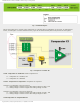
● 1 - Negative voltage reference is applied on the Vref- pin; and
● 0 - Voltage power supply Vss is used as negative voltage reference source.
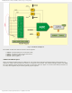
VCFG0 - Voltage Reference bit selects positive voltage reference source needed for A/D converter operating.
● 1 - Positive voltage reference is applied on the Vref+ pin; and
● 0 - Voltage power supply Vdd is used as positive voltage reference source.
In Short:
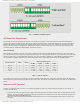
In order to measure voltage on an input pin by A/D converter the following should be done:
Step 1 - Configuring port:
● Write logic one (1) to the corresponding bit of the TRIS register to configure it as input; and
● Write logic one (1) to the corresponding bit of the ANSEL register to configure it as analog input.
Step 2 - Configuring ADC module:
● Configure voltage reference in the ADCON1 register;
● Select ADC conversion clock in the ADCON0 register;
● Select one of input channels CH0-CH13 of the ADCON0 register;
● Select data format using the ADFM bit of the ADCON1 register; and
● Enable A/D converter by setting the ADON bit of the ADCON0 register.
Step 3 - Configuring ADC interrupt (optionally):
● Clear the ADIF bit; and
● Set the ADIE, PEIE and GIE bits.
Step 4 - Wait for the required acquisition time (approximately 20uS) to pass.
Step 5 - Start conversion by setting the GO/DONE bit of the ADCON0 register.
Step 6 - Wait for ADC conversion to complete.
● It is necessary to check in program loop whether the GO/DONE pin is cleared or wait for an A/D interrupt (must be
previously enabled).
Step 7 - Read ADC results:
● Read the ADRESH and ADRESL registers.
Analog Comparator
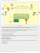
In addition to A/D converter, there is one more module, which until quite recently has been embedded only in integrated
circuits, belonging to so called analog electronics. Owing to the fact that it is hardly possible to find any more complex
automatic device which in some way does not use these circuits, two high quality comparators along with additional
electronics are integrated into the microcontroller and connected to its pins.
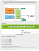
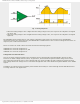
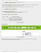
How does a comparator operate? Basically, the analog comparator is an amplifier which compares the magnitude of
voltages at two inputs. Looking at its physical features, it has two inputs and one output. Depending on which input has a
higher voltage (analog value), a logic zero (0) or logic one (1) (digital values) will appear on its output:
http://www.mikroe.com/en/books/picmcubook/ch7/ (6 of 14)5/3/2009 11:34:24 AM