
Specifications

mikroElektronika | Free Online Book | PIC Microcontrollers | Chapter 7: Analog Modules
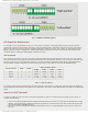
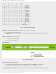
CHS3 CHS2 CHS1 CHS0 Channel Pin
0 0 0 0 0 RA0/AN0
0 0 0 1 1 RA1/AN1
0 0 1 0 2 RA2/AN2
0 0 1 1 3 RA3/AN3
0 1 0 0 4 RA5/AN4
0 1 0 1 5 RE0/AN5
0 1 1 0 6 RE1/AN6
0 1 1 1 7 RE2/AN7
1 0 0 0 8 RB2/AN8
1 0 0 1 9 RB3/AN9
1 0 1 0 10 RB1/AN10
1 0 1 1 11 RB4/AN11
1 1 0 0 12 RB0/AN12
1 1 0 1 13 RB5/AN13
1 1 1 0 CVref
1 1 1 1 Vref = 0.6V
Table 7-3 Analog Channel Status Bits
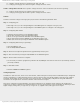
GO/DONE - A/D Conversion Status bit determines current status of conversion:
● 1 - A/D conversion is in progress; and
● 0 - A/D conversion is complete. This bit is automatically cleared by hardware when the A/D conversion is
completed.
ADON - A/D On bit enables A/D converter.
● 1 - A/D converter is enabled; and
● 0 - A/D converter is disabled.
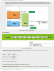
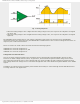
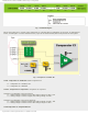
ADCON1 Register
Fig. 7-5 ADCON1 Register
ADFM - A/D Result Format Select bit
● 1 - Conversion result right justified. Six most significant bits of the ADRESLH are not used; and
● 0 - Conversion result left justified. Six least significant bits of the ADRESL are not used.
VCFG1 - Voltage Reference bit selects negative voltage reference source needed for A/D converter operating.
http://www.mikroe.com/en/books/picmcubook/ch7/ (5 of 14)5/3/2009 11:34:24 AM