
Specifications

mikroElektronika | Free Online Book | PIC Microcontrollers | Chapter 7: Analog Modules
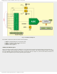
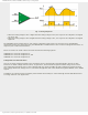
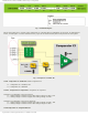
● Roughly speaking, voltage measurement in the converter is based on comparing input voltage with internal scale
which has 1024 marks (210=1024). The lowest scale mark stands for the Vref- voltage, whilst the highest mark
stands for the Vref+ voltage. Figure 7-3 below shows selectable referent voltages and their minimum and maximum
values as well.
Fig. 7-3 How to Use The A/D Converter
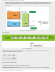
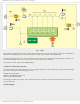
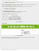
ADCON0 Register
Fig. 7-4 ADCON0 Register
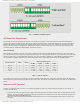
ADCS1, ADCS0 - A/D Conversion Clock Select bits select clock frequency used for internal synchronization of A/D
converter. It also affects duration of conversion.
ADCS1 ADCS2 Clock
0 0 Fosc/2
0 1 Fosc/8
1 0 Fosc/32
1 1 RC *
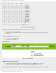
Table 7-2 A/D Conversion Select Bits
* Clock is generated by internal oscillator which is built in converter.
CHS3-CHS0 - Analog Channel Select bits select a pin or an analog channel for conversion, i.e. voltage measurement:
http://www.mikroe.com/en/books/picmcubook/ch7/ (4 of 14)5/3/2009 11:34:24 AM