
Specifications

mikroElektronika | Free Online Book | PIC Microcontrollers | Chapter 7: Analog Modules
● TOC
● Introduction
● Ch. 1
● Ch. 2
● Ch. 3
● Ch. 4
● Ch. 5
● Ch. 6
● Ch. 7
● Ch. 8
● Ch. 9
● App. A
● App. B
● App. C
Chapter 7: Analog Modules
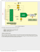
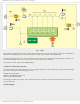
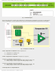
Apart from a large number of digital I/O lines, the PIC16F887 contains 14 analog inputs. They enable the microcontroller
to recognize, not only whether a pin is driven to logic zero or one (0 or +5V), but to precisely measure its voltage and
convert it into a numerical value, i.e. digital format. The whole procedure takes place in the A/D converter module which
has the following features:
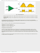
● The converter generates a 10-bit binary result using the method of successive approximation and stores the
conversion results into the ADC registers (ADRESL and ADRESH);
● There are 14 separate analog inputs;
● The A/D converter allows conversion of an analog input signal to a 10-bit binary representation of that signal; and
● By selecting voltage references Vref- and Vref+, the minimal resolution or quality of conversion may be adjusted to
various needs.
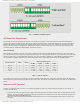
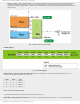
ADC Mode and Registers
Even though the use of A/D converter seems to be very complicated, it is basically very simple, simpler than using timers
and serial communication module, anyway.
http://www.mikroe.com/en/books/picmcubook/ch7/ (1 of 14)5/3/2009 11:34:24 AM