
Specifications

mikroElektronika | Free Online Book | PIC Microcontrollers | Chapter 6: Serial Communication Modules
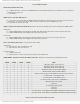
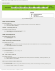
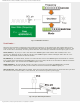
Fig. 6-24 SSPCON Register
WCOL Write Collision Detect bit
● 1 - Collision detected. A write to the SSPBUF register was attempted while the I²C conditions were not valid for a
transmission to start; and
● 0 - No collision.
SSPOV Receive Overflow Indicator bit
● 1 - A new byte is received while the SSPSR register still holds the previous data. Since there is no space for new
data receive, one of these two bytes must be cleared. In this case, data in SSPSR is lost; and
● 0 - Serial data is correctly received.
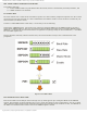
SSPEN - Synchronous Serial Port Enable bit determines the microcontroller pins function and initializes MSSP module:
In SPI mode
● 1 - Enables MSSP module and configures pins SCK, SDO, SDI and SS as the source of the serial port pins; and
● 0 - Disables MSSP module and configures these pins as I/O port pins.
In I²C mode
● 1 - Enables MSSP module and configures pins SDA and SCL as the source of the serial port pins; and
● 0 - Disables MSSP module and configures these pins as I/O port pins.
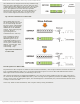
CKP - Clock Polarity Select bit is not used in I²C master mode.
In SPI mode
● 1 - Idle state for clock is a high level; and
● 0 - Idle state for clock is a low level.
In I²C slave mode
● 1 - Enables clock; and
● 0 - Holds clock low. Used to provide more time for data stabilization.
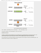
SSPM3-SSPM0 - Synchronous Serial Port Mode Select bits. SSP mode is determined by combining these bits:
SSPM3 SSPM2 SSPM1 SSPM0 Mode
0 0 0 0 SPI master mode, clock = Fosc/4
0 0 0 1 SPI master mode, clock = Fosc/16
0 0 1 0 SPI master mode, clock = Fosc/64
0 0 1 1 SPI master mode, clock = (output TMR)/2
0 1 0 0 SPI slave mode, SS pin control enabled
0 1 0 1 SPI slave mode, SS pin control disabled, SS can be used as I/O pin
0 1 1 0 I²C slave mode, 7-bit address used
0 1 1 1 I²C slave mode, 10-bit address used
1 0 0 0 I²C master mode, clock = Fosc / [4(SSPAD+1)]
1 0 0 1 Mask used in I²C slave mode
1 0 1 0 Not used
1 0 1 1 I²C controlled master mode
1 1 0 0 Not used
1 1 0 1 Not used
1 1 1 0 I²C slave mode, 7-bit address used,START and STOP bits enable interrupt
1 1 1 1 I²C slave mode, 10-bit address used,START and STOP bits enable interrupt
Table 6-3 Synchronous Serial Port Mode Select Bits
http://www.mikroe.com/en/books/picmcubook/ch6/ (21 of 27)5/3/2009 11:34:00 AM