
Specifications
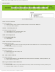

mikroElektronika | Free Online Book | PIC Microcontrollers | Chapter 6: Serial Communication Modules
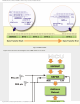
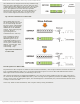
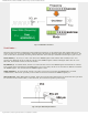
Fig. 6-22 MSSP Block Diagram in I²C Mode
The MSSP module uses six registers for I²C operation. Some of them are shown in figure above:
● SSPCON;
● SSPCON2;
● SSPSTAT;
● SSPBUF;
● SSPSR; and
● SSPADD.
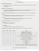
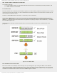
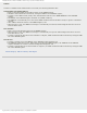
SSPSTAT Register
Fig. 6-23 SSPSTAT Register
SMP Sample bit
SPI master mode - This bit determines input data phase.
● 1 - Logic state is read at end of data output time; and
● 0 - Logic state is read in the middle of data output time.
SPI slave mode This bit must be cleared when SPI is used in Slave mode.
I²C mode (master or slave)
● 1 - Slew rate control disabled for standard speed mode (100kHz); and
● 0 - Slew rate control enabled for high speed mode (400kHz).
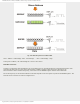
CKE - Clock Edge Select bit selects synchronization mode.
CKP = 0:
● 1 - Data is transmitted on rising edge of clock pulse (0 - 1); and
● 0 - Data is transmitted on falling edge of clock pulse (1 - 0).
http://www.mikroe.com/en/books/picmcubook/ch6/ (19 of 27)5/3/2009 11:33:59 AM