
Specifications

mikroElektronika | Free Online Book | PIC Microcontrollers | Chapter 6: Serial Communication Modules
frequency (so called high-speed I²C bus), but the clock frequency of the most frequently used protocol is limited to 100
KHz. There is no limit in case of minimal frequency.
When master and slave components are synchronized by the clock, every data exchange is always initialized by master.
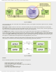
Once the MSSP module has been enabled, it waits for a Start condition to occur. First the master device sends the START
bit (logic zero) through the SDA pin, then the 7-bit address of the selected slave device, and finally, the bit which requires
data write (0) or read (1) to that device. Accordingly, following the start condition, the eight bits are shifted into the
SSPSR register. All slave devices share the same transmission line and all will simultaneously receive the first byte, but
only one of them has the address to match.
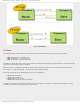
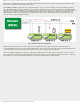
Fig. 6-20 Master and Slave Configuration
Once the first byte has been sent (only 8-bit data are transmitted), master goes into receive mode and waits for
acknowledgment from the receive device that address match has occurred. If the slave device sends acknowledge data bit
(1), data transfer will be continued until the master device (microcontroller) sends the Stop bit.
This is the simplest explanation of how two components communicate. If needed, this microcontroller is able to control
more complicated situations when 1024 different components, shared by several different master devices, are connected.
Such devices are rarely used in practice and there is no need to discuss them at greater length.
http://www.mikroe.com/en/books/picmcubook/ch6/ (17 of 27)5/3/2009 11:33:59 AM