
Specifications

mikroElektronika | Free Online Book | PIC Microcontrollers | Chapter 6: Serial Communication Modules
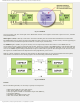
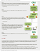
Fig. 6-13 SPI Mode
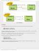
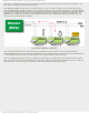
As seen in figure 6-14, the central part of the SPI module consists of two registers connected to pins for receive, transmit
and synchronization.
Shift register (SSPRS) is directly connected to the microcontroller pins and used for data transmission in serial format.
The SSPRS register has its input and output and shifts the data in and out of device. In other words, each bit appearing on
input (receive line) simultaneously shifts another bit toward output (transmit line).
The SSPBUF register (Buffer) is a part of memory used to temporarily hold the data written to the SSPRS until the
received data is ready. Upon receiving all 8 bits of data, that byte is moved to the SSPBUF register. This double buffering
of the received data (SSPBUF) allows the next byte to start reception before reading the data that was just received. Any
write to the SSPBUF register during transmission/reception of data will be ignored. Since having been the most accessed,
this register is considered the most important from the programmers’ point of view.
Namely, if mode settings are neglected, data transfer via SPI actually means to write and read data from this register,
while another "acrobatics" such as moving registers are automatically performed by hardware.
Fig. 6-14 SPI Mode
In short:
Prior to initializing the SPI, it is necessary to specify several options:
● Master mode (SCK pin is the clock output);
● Slave mode (SCK pin is the clock input);
● Data input phase- middle or end of data output time (SMP bit);
● Clock edge (CKE bit);
● Baud Rate (only in Master mode); and
● Slave select mode (Slave mode only).
http://www.mikroe.com/en/books/picmcubook/ch6/ (15 of 27)5/3/2009 11:33:59 AM