
Specifications

mikroElektronika | Free Online Book | PIC Microcontrollers | Chapter 6: Serial Communication Modules
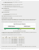
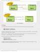
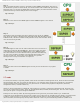
Fig.6-12 MSSP Module
SPI Mode
The SPI mode allows 8 bits of data to be transmitted and received simultaneously using 3 input/output lines:
● SDO - Serial Data Out - transmit line;
● SDI - Serial Data In - receive line; and
● SCK - Serial Clock - synchronization line.
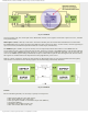
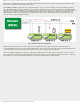
In addition to these three lines, if the microcontroller exchanges data with several peripheral devices, the forth line (SS)
may be also used. Refer to figure 6-13 below.
SS - Slave Select - is additional pin used for specific device selection. It is active only in case the microcontroller is in
slave mode, i.e. when the external - master device requires data exchange.
When operating in SPI mode, MSSP module uses in total of 4 registers:
● SSPSTAT status register;
● SSPCON control register;
● SSPBUF buffer register; and
● SSPSR shift register (not directly available)
The first three registers are writable/readable and can be changed at any moment, while the forth register, since not
available, is used for converting data into "serial" format.
http://www.mikroe.com/en/books/picmcubook/ch6/ (14 of 27)5/3/2009 11:33:59 AM