
Specifications

mikroElektronika | Free Online Book | PIC Microcontrollers | Chapter 6: Serial Communication Modules
5. If needed the bit TXEN causes an interrupt, the GIE and PEIE bits of the INTCON register should be set;
6. On 9-bit data transmission, value of the ninth bit should be written to the TX9D bit of the TXSTA register; and
7. Transmission starts by writing 8-bit data to the TXREG register.
Receiving data via asynchronous EUSART communication:
1. Baud Rate should be set by using bits BRGH (TXSTA register) and BRG16 (BAUDCTL register) and registers SPBRGH
and SPBRG;
2. The SYNC bit (TXSTA register) should be cleared and the SPEN bit should be set (RCSTA register) in order to enable
serial port;
3. If it is necessary the data receive causes an interrupt, both the RCIE bit of the PIE1 register and bits GIE and PEIE of
the INTCON register should be set;
4. On 9-bit data receive, the RX9 bit of the RCSTA register should be set;
5. Data receive should be enabled by setting the CREN bit of the RCSTA register;
6. The RCSTA register should be read to get information on possible errors which have occurred during transmission.
On 9-bit data receive, the ninth bit will be stored in this register; and
7. Received 8-bit data stored in the RCREG register should be read.
Setting Address Detection Mode:
1. Baud Rate should be set by using bits BRGH (TXSTA register) and BRG16 (BAUDCTL register) and registers SPBRGH
and SPBRG;
2. The SYNC bit (TXSTA register) should be cleared and the SPEN bit should be set (RCSTA register) in order to enable
serial port;
3. If it is necessary the data receive causes an interrupt, the RCIE bit of the PIE1 bit as well as bits GIE and PEIE of the
INTCON register should be set;
4. The RX9 bit of the RCSTA register should be set;
5. The ADDEN of the RCSTA register should be set, which enables a data to be interpreted as address;
6. Data receive is enabled by setting the CREN bit of the RCSTA register;
7. Immediately upon 9-bit data is received, the RCIF bit of the PIR1 register will be automatically set. If enabled, an
interrupt occurs;
8. The RCSTA register should be read in order to get information on possible errors which have occurred during
transmission. The ninth bit RX9D is always set; and
9. Received 8-bits stored in the RCREG register should be read. It should be checked whether the combination of
these bits matches the predefined address. If the match occurs, it is necessary to clear the ADDEN bit of the RCSTA
register, which enables further 8-bit data receive.
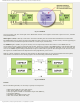
Master Synchronous Serial Port Module
MSSP module (Master Synchronous Serial Port) is a very useful, but at the same time one of the most complex circuit
within the microcontroller. It enables high speed communication between a microcontroller and other peripherals or
microcontroller devices by using few input/output lines (maximum two or three). Therefore, it is commonly used to
connect the microcontroller to LCD displays, A/D converters, serial EEPROMs, shift registers etc. The main feature of this
type of communication is that it is synchronous and suitable for use in systems with a single master and one or more
slaves. A master device contains the necessary circuitry for baud rate generation and supplies the clock for all devices in
the system. Slave devices may in that way eliminate the internal clock generation circuitry. The MSSP module can operate
in one of two modes:
● SPI mode (Serial Peripheral Interface)
● I²C mode (Inter-Integrated Circuit)
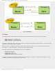
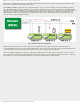
As seen in figure 6-12 below, one MSSP module represents only a half of the hardware needed to establish serial
communication, while another half is stored in the device the data is exchanged with. Even though the modules on both
ends of the line are the same, their modes are essentially different depending on whether they operate as a Master or a
Slave:
If the microcontroller to be programmed controls another device or circuit (peripherals), it should operate as a master
device. A module defined as such will generate clock when needed, i.e. only when data receive and transmit is required
by the software. It depends on the master whether the connection will be established or not. Otherwise, if the
microcontroller to be programmed is a part of some peripheral which belongs to some more complex device (for example
PC), then it should operate as a slave device. As such, it always has to wait for request for data transfer from master
device.
http://www.mikroe.com/en/books/picmcubook/ch6/ (13 of 27)5/3/2009 11:33:59 AM