
Specifications

mikroElektronika | Free Online Book | PIC Microcontrollers | Chapter 6: Serial Communication Modules
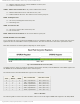
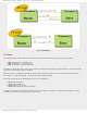
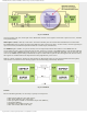
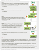
Fig. 6-11 BAUDCTL Register
ABDOVF - Auto-Baud Detect Overflow bit is only used in asynchronous mode during baud rate detection.
● 1 - Auto-baud timer overflowed; and
● 0 - Auto-baud timer did not overflow.
RCIDL - Receive Idle Flag bit is only used in asynchronous mode.
● 1 - Receiver is idle; and
● 0 - START bit has been received and receiving is in progress.
SCKP - Synchronous Clock Polarity Select bit acts differently depending on EUSART mode.
Asynchronous mode:
● 1 - Transmit inverted data to the RC6/TX/CK pin; and
● 0 - Transmit non-inverted data to the same pin.
Synchronous mode:
● 1 - Synchronization on rising edge of the clock; and
● 0 - Synchronization on falling edge of the clock.
WUE Wake-up Enable bit
● 1 - Receiver waits for a falling edge on the RC7/RX/DT pin to start waking up the microcontroller from sleep mode;
and
● 0 - Receiver operates normally.
ABDEN - Auto-Baud Detect Enable bit is used in asynchronous mode only.
● 1 - Auto-baud detect mode is enabled. Bit is automatically cleared on baud rate detect; and
● 0 - Auto-baud detect mode is disabled.
In Short:
Sending data via asynchronous EUSART communication:
1. The desired baud rate should be set by using bits BRGH (TXSTA register) and BRG16 (BAUDCTL register) and
registers SPBRGH and SPBRG;
2. The SYNC bit (TXSTA register) should be cleared and the SPEN bit should be set (RCSTA register) in order to enable
serial port;
3. On 9-bit data transmission, the TX9 bit of the TXSTA register should be set;
4. Data transmission is enabled by setting bit TXEN of the TXSTA register. Bit TXIF of the PIR1 register is automatically
set;
http://www.mikroe.com/en/books/picmcubook/ch6/ (12 of 27)5/3/2009 11:33:59 AM