
Specifications

mikroElektronika | Free Online Book | PIC Microcontrollers | Chapter 6: Serial Communication Modules
● 1 - Enables continuous receive until the CREN bit is cleared; and
● 0 - Disables continuous receive.
ADDEN - Address Detect Enable bit is only used in address detect mode.
● 1 - Enables address detection on 9-bit data receive; and
● 0 - Disables address detection. The ninth bit can be used as parity bit.
FERR - Framing Error bit
● 1 - On receive, Framing Error is detected; and
● 0 - No framing error.
OERR - Overrun Error bit.
● 1 - On receive, Overrun Error is detected; and
● 0 - No overrun error.
RX9D - Ninth bit of Received Data can be used as address or parity bit.
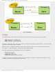
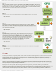
EUSART Baud Rate Generator (BRG)
If you carefully look at the asynchronous EUSART receiver or transmitter diagram, you will see, in both cases, that clock
signal from the local timer BRG is used for synchronization. The same clock source is also used in synchronous mode.
This timer consists of two 8-bit registers comprising one 16-bit register.
Fig. 6-10 EUSART Baud Rate Generator (BRG)
A number written to these two registers determines the baud rate. Besides, both the BRGH bit of the TXSTA register and
the BRGH16 bit of the BAUDCTL register affect clock frequency.
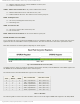
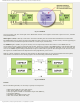
The formula used to determine Baud Rate is given in the table below.
Bits
BRG / EUSART Mode Baud Rate Formula
SYNC BRG1G BRGH
0 0 0 8-bit / asynchronous Fosc / [64 (n + 1)]
0 0 1 8-bit / asynchronous Fosc / [16 (n + 1)]
0 1 0 16-bit / asynchronous Fosc / [16 (n + 1)]
0 1 1 16-bit / asynchronous Fosc / [4 (n + 1)]
1 0 X 8-bit / asynchronous Fosc / [4 (n + 1)]
1 1 X 16-bit / asynchronous Fosc / [4 (n + 1)]
Table 6-1 Baud Rate
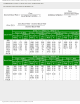
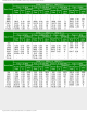
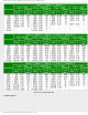
The following tables contain values that should be written to the 16-bit register SPBRG and assigned to the SYNC, BRGH
http://www.mikroe.com/en/books/picmcubook/ch6/ (8 of 27)5/3/2009 11:33:59 AM