Programming PIC Microcontrollers in BASIC - mikroElektronika Table of Contents ● Preface ● Chapter 1: The Basics ● Chapter 2: Elements of BASIC Language ● Chapter 3: Operators ● Chapter 4: Control Structures ● Chapter 5: Built-in and Library Routines ● Chapter 6: Examples with PIC Integrated Peripherals ● Chapter 7: Examples with Displaying Data ● Chapter 8: Examples with Memory and Storage Media ● ● Chapter 9: Communications Examples (under construction) Appendix A: mikroBasic IDE Pref
Programming PIC Microcontrollers in BASIC - mikroElektronika within the PN junctions escapes your knowledge. You are not supposed to know the whole history of electronics in order to assure the income for you or your family. Do not expect that you will find everything you need in a single book, though. The information are dispersed literally everywhere around us, so it is necessary to collect them diligently and sort them out carefully. If you do so, the success is inevitable.
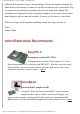
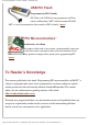
Programming PIC Microcontrollers in BASIC - mikroElektronika USB PIC Flash Programmer for PIC18 family PIC Flash is the USB In-System programmer for Flash family of Microchip’s MCUs. Beside standard FLASH MCUs, it can also program the latest models of PIC18 family. [more] “PIC Microcontrollers” On-line book, 3rd edition The purpose of the book is not to make a microcontroller expert out of you, but to make you equal to those who had somebody to ask.
Programming PIC Microcontrollers in BASIC - mikroElektronika PIC, PIC, PICmicro, and MPLAB are registered and protected trademarks of the Microchip Technology Inc. USA. Microchip logo and name are the registered tokens of the Microchip Technology. mikroBasic is a registered trade mark of mikroElektronika. All other tokens mentioned in the book are the property of the companies to which they belong. mikroElektronika © 1998 - 2004. All rights reserved. If you have any questions, please contact our office.
Programming PIC Microcontrollers in BASIC - mikroElektronika Chapter 1: The Basics ● Introduction ● 1.1 Why BASIC? ● 1.2 Choosing the right PIC for the task ● 1.3 A word about code writing ● 1.4 Writing and compiling your program ● 1.5 Loading program to microcontroller ● 1.6 Running the program ● 1.
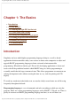
Programming PIC Microcontrollers in BASIC - mikroElektronika attention particularly to programming of microcontrollers. Program consists of a sequence of commands written in programming language that microcontroller executes one after another. Chapter 2 deals with the structure of BASIC program in details. Compiler is a program run on computer and its task is to translate the original BASIC code into language of zeros and ones that can be fed to microcontroller.
Programming PIC Microcontrollers in BASIC - mikroElektronika 1.1 Why BASIC? Originally devised as an easy-to-use tool, BASIC became widespread on home microcomputers in the 1980s, and remains popular to this day in a handful of heavily evolved dialects. BASIC’s name, coined in classic, computer science tradition to produce a nice acronym, stands for Beginner’s All-purpose Symbolic Instruction Code. BASIC is still considered by many PC users to be the easiest programming language to use.
Programming PIC Microcontrollers in BASIC - mikroElektronika 1.2 Choosing the right PIC for the task Currently, the best choice for application development using BASIC are: the famous PIC16F84, PIC16F87x, PIC16F62x, PIC18Fxxx. These controllers have program memory built on FLASH technology which provides fast erasing and reprogramming, thus allowing fast debugging.
Programming PIC Microcontrollers in BASIC - mikroElektronika mikroBasic IDE includes highly adaptable Code Editor, fashioned to satisfy needs of both novice users and experienced programmers. Syntax Highlighting, Code Templates, Code & Parameter Assistant, Auto Correct for common typos, and other features provide comfortable environment for writing a program. If you had no previous experience with advanced IDEs, you may wonder what Code and Parameter Assistants do.
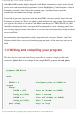
Programming PIC Microcontrollers in BASIC - mikroElektronika end. When the program is completed and saved as .pbas file, it can be compiled by clicking on Compile Icon (or just hit CTRL+F9) in mikroBasic IDE. The compiling procedure takes place in two consecutive steps: 1. Compiler will convert .pbas file to assembly code and save it as blink.asm file. 2. Then, compiler automatically calls assembly, which converts .asm file into executable HEX code ready for feeding to microcontroller.
Programming PIC Microcontrollers in BASIC - mikroElektronika HEX file is the one you need to program the microcontroller. Commonly, generated HEX will be standard 8-bit Merged Intel HEX format, accepted by the vast majority of the programming software. The programming device (programmer) with accessory software installed on PC is in charge of writing the physical contents of HEX file into the internal memory of a microcontroller. The contents of a file blink.
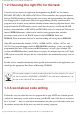
Programming PIC Microcontrollers in BASIC - mikroElektronika Note that the programming software should be used only for the communication with the programming device — it is not suitable for code writing. 1.6 Running the program For proper functioning of microcontroller, it is necessary to provide power supply, oscillator, and a reset circuit. The supply can be set with the simple rectifier with Gretz junction and LM7805 circuit as shown in the figure below.
Programming PIC Microcontrollers in BASIC - mikroElektronika reset circuit — MCLR pin is connected to +5V through a 10K resistor. Below is the scheme of a rectifier with LM7805 circuit which gives the output of stable +5V, and the minimal configuration relevant for the operation of a PIC microcontroller. After the supply is brought to the circuit previously shown, PIC microcontroller should look animated, and the LED diode should blink once every second.
Programming PIC Microcontrollers in BASIC - mikroElektronika and as such is not suitable for the supply of microcontroller. To avoid the pulsating, the electrolytic capacitor of high capacitance (e.g. 470 mF) is placed at the rectifier output. ● If PIC microcontroller supervises devices that pull a lot of energy, they may provoke enough malfunctioning on the supply lines to cause the microcontroller start behaving somewhat strangely.
Programming PIC Microcontrollers in BASIC - mikroElektronika mikroElektronika © 1998 - 2004. All rights reserved. If you have any questions, please contact our office. http://www.mikroelektronika.co.yu/english/product/books/picbasicbook/01.
Programming PIC Microcontrollers in BASIC - mikroElektronika Chapter 2: Elements of BASIC Language ● Introduction ● 2.1 Identifiers ● 2.2 Operators ● 2.3 Expressions ● 2.4 Instructions ● 2.5 Data Types ● 2.6 Constants ● 2.7 Variables ● 2.8 Symbols ● 2.9 Directives ● 2.10 Comments ● 2.11 Labels ● 2.12 Procedures and Functions ● 2.13 Modules Introduction This chapter deals with the elements of BASIC language and the ways to use them efficiently.
Programming PIC Microcontrollers in BASIC - mikroElektronika program LED_Blinking main: ' Beginning of program TRISB = 0 ' Configure pins of PORTB as output PORTB = %11111111 ' Turn ON diodes on PORTB Delay_ms(1000) ' Wait for 1 second PORTB = %00000000 ' Turn OFF diodes on PORTB Delay_ms(1000) ' Wait for 1 second goto main ' Endless loop end.
Programming PIC Microcontrollers in BASIC - mikroElektronika 2.2 Operators BASIC language possesses set of operators which is used to assign values, compare values, and perform other operations. The objects manipulated for that purpose are called operands (which themselves can be variables, constants, or other elements). Operators in BASIC must have at least two operands, with an exception of two unary operators. They serve to create expressions and instructions that in effect compose the program.
Programming PIC Microcontrollers in BASIC - mikroElektronika goto Minute ' If variable Time equals 60 jump to label Minute end if Instruction if..then contains the conducting expression Time = 60 composed of two operands, variable Time, constant 60 and the comparison operator (=). Generally, instructions may be divided into conditional instructions (decision making), loops (repeating blocks), jumps, and specific built-in instructions (e.g. for accessing the peripherals of microcontroller).
Programming PIC Microcontrollers in BASIC - mikroElektronika Signed can hold both positive and negative numbers: short -128 .. 127 integer -32768 .. 32767 longint -2147483648 .. 214748364 2.6 Constants Constant is data whose value cannot be changed during the runtime. Every constant is declared under unique name which must be a valid identifier. It is a good practice to write constant names in uppercase.
Programming PIC Microcontrollers in BASIC - mikroElektronika In BASIC, variable needs to be declared before it can be used. Specifying a data type for each variable is mandatory. Variable is declared like this: dim identifier as type where identifier is any valid identifier and type can be any given data type.
Programming PIC Microcontrollers in BASIC - mikroElektronika end if PORT.1 = 0 DELAY1S ... Note that using a symbol in a program technically consumes no RAM memory – compiler simply replaces each instance of a symbol with the appropriate code from the declaration. 2.9 Directives Directives are words of special significance for BASIC, but unlike other reserved words, appear only in contexts where user-defined identifiers cannot occur. You cannot define an identifier that looks exactly like a directive.
Programming PIC Microcontrollers in BASIC - mikroElektronika 2.10 Comments Comments are text that is added to the code for purpose of description or clarification, and are completely ignored by the compiler. ' Any text between an apostrophe and the end of the ' line constitutes a comment. May span one line only. It is a good practice to comment your code, so that you or anybody else can later reuse it.
Programming PIC Microcontrollers in BASIC - mikroElektronika program test main: ' some instructions... ' simple endless loop using a label my_loop: ' some instructions... ' now jump back to label _loop goto my_loop end. Note: Although it might seem like a good idea to beginners to program by means of jumps and labels, you should try not to depend on it. This way of thinking strays from the procedural programming and can teach you bad programming habits.
Programming PIC Microcontrollers in BASIC - mikroElektronika calling the procedure, and (parameterList), and localDeclarations are optional declaration of variables and/or constants. sub procedure pr1_procedure(dim par1 as byte, dim par2 as byte, dim byref vp1 as byte, dim byref vp2 as byte) dim locS as byte par1 = locS + par1 + par2 vp1 = par1 or par2 vp2 = locS xor par1 end sub par1 and par2 are passed to the procedure by the value, but variables marked by keyword byref are passed by the address.
Programming PIC Microcontrollers in BASIC - mikroElektronika locS = par1 * (par2 + 1) Result = locS end sub As functions return values, function calls are technically expressions. For example, if you have defined a function called Calc, which collects two integer arguments and returns an integer, then the function call Calc(24, 47) is an integer expression. If I and J are integer variables, then I + Calc(J, 8) is also an integer expression. 2.
Programming PIC Microcontrollers in BASIC - mikroElektronika Keyword include instructs the compiler which file to compile. The example above includes module math2. pbas in the program file. Obviously, routine sqrt used in the example is declared in module math2.pbas. If you want to distribute your module without disclosing the source code, you can send your compiled library (file extension .mcl). User will be able to use your library as if he had the source code.
Programming PIC Microcontrollers in BASIC - mikroElektronika Chapter 3: Operators ● Introduction ● 3.1 Arithmetic Operators ● 3.2 Boolean Operators ● 3.3 Logical (Bitwise) Operators ● 3.4 Relation Operators (Comparison Operators) Introduction In complex expressions, operators with higher precedence are evaluated before the operators with lower precedence; operators of equal precedence are evaluated according to their position in the expression starting from the left.
Programming PIC Microcontrollers in BASIC - mikroElektronika Operator + - * div mod Operation addition subtraction multiplication division remainder Operand types Result type byte, short, integer, words, byte, short, integer, words, longint longint byte, short, byte, short, integer, words, longint integer, words, longint byte, short, integer, words, integer, words long byte, short, byte, short, integer, words integer, words byte, short, byte, short, integer, words integer, wo
Programming PIC Microcontrollers in BASIC - mikroElektronika BASIC also has two unary arithmetic operators: Operator Operation Operand types Result type + (unary) sign identity short, integer, longint short, integer, longint - (unary) sign negation short, integer, short, integer, longint longint Unary arithmetic operators can be used to change sign of variables: a = 3 b = -a ' assign value -3 to b 3.
Programming PIC Microcontrollers in BASIC - mikroElektronika if (astr > 10) and (astr < 20) then PORTB = 0xFF end if 3.
Programming PIC Microcontrollers in BASIC - mikroElektronika (must be positive and less then 255). >> : shift right the operand for a number of bit places specified in the right operand (must be positive and less then 255). For example, if you need to extract the higher byte, you can do it like this: dim temp as word main: TRISA = word(temp >> 8) end. 3.
Programming PIC Microcontrollers in BASIC - mikroElektronika PIC, PIC, PICmicro, and MPLAB are registered and protected trademarks of the Microchip Technology Inc. USA. Microchip logo and name are the registered tokens of the Microchip Technology. mikroBasic is a registered trade mark of mikroElektronika. All other tokens mentioned in the book are the property of the companies to which they belong. mikroElektronika © 1998 - 2004. All rights reserved. If you have any questions, please contact our office.
Programming PIC Microcontrollers in BASIC - mikroElektronika Chapter 4: Control Structures ● Introduction ● 4.1 Conditional Statements ● 4.1.1 IF..THEN Statement ● 4.1.2 SELECT..CASE Statement ● 4.1.3 GOTO Statement ● 4.2 Loops ● 4.2.1 FOR Statement ● 4.2.2 DO..LOOP Statement ● 4.2.3 WHILE Statement ● 4.3 ASM Statement Introduction Statements define algorithmic actions within a program.
Programming PIC Microcontrollers in BASIC - mikroElektronika condition. The BASIC instruction of branching in BASIC language is the IF instruction, with several variations that provide the necessary flexibility. 4.1.1 IF..THEN Statement – conditional program branching Syntax if expression then statements1 [ else statements2 ] end if Description Instruction selects one of two possible program paths. Instruction IF..
Programming PIC Microcontrollers in BASIC - mikroElektronika if PORTB.0 = 0 then goto Add end if goto Main Add: j = j + 1 end. More complex form of instruction is program branching with the ELSE clause: dim j as byte Main: if PORTB.0 = 0 then j = j + 1 else j = j - 1 endif goto Main http://www.mikroelektronika.co.yu/english/product/books/picbasicbook/04.
Programming PIC Microcontrollers in BASIC - mikroElektronika end. 4.1.2 SELECT..CASE Statement – Conditional multiple program branching Syntax select case Selector case Value_1 Statements_1 case Value_2 Statements_2 ... case Value_N Statements_n [ case else Statements_else ] end select Description Select Case statement is used for selecting one of several available branches in the program course. It consists of a selector variable as a switch condition, and a list of possible values.
Programming PIC Microcontrollers in BASIC - mikroElektronika Example select case W case 0 B = 1 PORTB = B case 1 A = 1 PORTA = A case else PORTB = 0 end select ... select case Ident case testA PORTB = 6 Res = T mod 23 case teB + teC T = 1313 case else T = 0 end select 4.1.3 GOTO Statement – Unconditional jump to the specified label Syntax goto Label Description Goto statement jumps to the specified label unconditionally, and the program execution continues normally from that point on.
Programming PIC Microcontrollers in BASIC - mikroElektronika Example program test main: ' some instructions ... goto myLabel ' some instructions... myLabel: ' some instructions... end. 4.2 Loops Loop statements allow repeating one or more instructions for a number of times. The conducting expression determines the number of iterations loop will go through. 4.2.1 FOR Statement – Repeating of a program segment Syntax for counter = initialValue to finalValue [step step_value] statement_1 statement_2 ...
Programming PIC Microcontrollers in BASIC - mikroElektronika Description For statement requires you to specify the number of iterations you want the loop to go through. Counter is variable; initialValue and finalValue are expressions compatible with counter; statement is any statement that does not change the value of counter; step_value is value that is added to the counter in each iteration. Step_value is optional, and defaults to 1 if not stated otherwise.
Programming PIC Microcontrollers in BASIC - mikroElektronika Example I = 0 do I = I + 1 ' execute these 2 statements PORTB = I ' until i equals 10 (ten) loop until I = 10 4.2.3 WHILE Statement – Loop while condition is fulfilled Syntax while expression statement_0 statement_1 ... statement_N wend Description Expression is tested first. If it returns True, all the following statements enclosed by while and wend will be executed (or only one statement, alternatively).
Programming PIC Microcontrollers in BASIC - mikroElektronika wend 4.3 ASM Statement – Embeds assembly instruction block Syntax asm statementList end asm Description Sometimes it can be useful to write part of the program in assembly. ASM statement can be used to embed PIC assembly instructions into BASIC code. Note that you cannot use numerals as absolute addresses for SFR or GPR variables in assembly instructions.
Programming PIC Microcontrollers in BASIC - mikroElektronika Chapter 5: Built-in and Library Routines ● Introduction ● 5.1 Built-in Routines ● 5.1.1 SetBit ● ● 5.2.6 EEPROM Library ● 5.2.13 PWM Library ● 5.2.6.1 EEPROM_Read ● 5.2.13.1 PWM_Init ● 5.2.6.2 EEPROM_Write ● 5.2.13.2 PWM_Change_Duty ● 5.2.13.3 PWM_Start ● 5.2.13.4 PWM_Stop ● 5.2.14 RS485 Library ● 5.2.14.1 RS485Master_Init ● 5.2.7 Flash Memory Library 5.1.2 ClearBit ● 5.2.7.1 Flash_Read ● 5.1.3 TestBit ● 5.2.7.
Programming PIC Microcontrollers in BASIC - mikroElektronika ● 5.2 Library Routines ● 5.2.9.1 LCD_Init ● 5.2.15.3 SPI_Read ● 5.2.9.2 LCD_Config ● 5.2.15.4 SPI_Write ● 5.2.1 Numeric Formatting ● 5.2.9.3 LCD_Chr ● 5.2.1.1 ByteToStr ● 5.2.9.4 LCD_Chr_CP ● 5.2.16 USART Library ● 5.2.1.2 WordToStr ● 5.2.9.5 LCD_Out ● 5.2.16.1 USART_Init ● 5.2.1.3 ShortToStr ● 5.2.9.6 LCD_Out_CP ● 5.2.16.2 USART_Data_Ready ● 5.2.1.4 IntToStr ● 5.2.9.7 LCD_Cmd ● 5.2.16.3 USART_Read ● 5.2.1.
Programming PIC Microcontrollers in BASIC - mikroElektronika ● ● ● ● ● 5.2.11.8 GLCD_Clear_Dot ● 5.2.11.9 GLCD_Set_Dot ● 5.2.11.10 GLCD_Circle ● 5.2.11.11 GLCD_Line ● 5.2.11.12 GLCD_Invert ● ● 5.2.20 Software UART Library ● 5.2.20.1 Soft_UART_Init ● 5.2.20.2 Soft_UART_Read ● 5.2.20.3 Soft_UART_Write 5.2.11.13 GLCD_Goto_XY ● 5.2.21 Sound Library ● 5.2.11.14 GLCD_Put_Char ● 5.2.21.1 Sound_Init ● 5.2.11.15 GLCD_Clear_Screen ● 5.2.21.2 Sound_Play ● 5.2.11.16 GLCD_Put_Text ● 5.
Programming PIC Microcontrollers in BASIC - mikroElektronika Introduction BASIC was designed with focus on simplicity of use. Great number of built-in and library routines are included to help you develop your applications quickly and easily. 5.1 Built-in Routines BASIC incorporates a set of built-in functions and procedures. They are provided to make writing programs faster and easier. You can call built-in functions and procedures in any part of the program. 5.1.
Programming PIC Microcontrollers in BASIC - mikroElektronika 5.1.2 ClearBit – Clears the specified bit Prototype sub procedure ClearBit(dim byref Reg as byte, dim Bit as byte) Description Clears of register . Any SFR (Special Function Register) or variable of byte type can pass as valid variable parameter, but constants should be in range [0..7]. Example ClearBit(PORTC,7) ' clear bit RC7 5.1.
Programming PIC Microcontrollers in BASIC - mikroElektronika Prototype sub function Lo(dim Par as byte..longint) as byte Description Returns byte 0 of , assuming that word/integer comprises bytes 1 and 0, and longint comprises bytes 3, 2, 1, and 0. Example Lo(A) ' returns lower byte of variable A 5.1.5 Hi – Extract one byte from the specified parameter Prototype sub function Hi(dim arg as word..
Programming PIC Microcontrollers in BASIC - mikroElektronika Example Higher(Aaaa) ' returns byte next to the highest byte of variable Aaaa 5.1.7 Highest – Extract one byte from the specified parameter Prototype sub function Highest(dim arg as longint) as byte Description Returns byte 3 of , assuming that longint comprises bytes 3, 2, 1, and 0. Example Highest(Aaaa) ' returns the highest byte of variable Aaaa 5.1.
Programming PIC Microcontrollers in BASIC - mikroElektronika Prototype sub procedure Delay_ms(const Count as word) Description Routine creates a software delay in duration of milliseconds. Example Delay_ms(1000) ' creates software delay equal to 1s 5.1.10 Inc – Increases variable by 1 Prototype sub procedure Inc(byref Par as byte..longint) Description Routine increases by one. Example Inc(Aaaa) ' increments variable Aaaa by 1 5.1.
Programming PIC Microcontrollers in BASIC - mikroElektronika Example Dec(Aaaa) ' decrements variable Aaaa by 1 5.1.12 Length – Returns length of string Prototype sub function Length(dim Text as string) as byte Description Routine returns length of string as byte. Example Length(Text) ' returns string length as byte 5.2 Library Routines A comprehensive collection of functions and procedures is provided for simplifying the initialization and use of PIC MCU and its hardware modules.
Programming PIC Microcontrollers in BASIC - mikroElektronika 5.2.1.1 ByteToStr – Converts byte to string Prototype sub procedure ByteToStr(dim input as byte, dim byref txt as char[6]) Description Parameter represents numerical value of byte type that should be converted to string; parameter is passed by the address and contains the result of conversion. Parameter has to be of sufficient size to fit the converted string.
Programming PIC Microcontrollers in BASIC - mikroElektronika Example WordToStr(Counter, Message) ' Copies value of word Counter into string Message 5.2.1.3 ShortToStr – Converts short to string Prototype sub procedure ShortToStr(dim input as short, dim byref txt as char[6]) Description Parameter represents numerical value of short type that should be converted to string; parameter is passed by the address and contains the result of conversion.
Programming PIC Microcontrollers in BASIC - mikroElektronika Description Parameter represents numerical value of integer type that should be converted to string; parameter is passed by the address and contains the result of conversion. Parameter has to be of sufficient size to fit the converted string. Example IntToStr(Counter, Message) ' Copies value of integer Counter into string Message 5.2.1.
Programming PIC Microcontrollers in BASIC - mikroElektronika Prototype sub procedure Dec2Bcd(dim dec_num as byte) as byte Description Function converts 8-bit decimal numeral to BCD and returns the result as byte. Example dim a as byte dim b as byte ... a = 224 b = Dec2Bcd(a) ' b equals 140 now 5.2.1.
Programming PIC Microcontrollers in BASIC - mikroElektronika 5.2.1.8 Bcd2Dec – Converts 16-bit BCD value to decimal Prototype sub procedure Dec2Bcd16(dim dec_num as word) as word Description Function converts 16-bit decimal numeral to BCD and returns the result as word. Example dim a as word dim b as word ... a = 4660 b = Dec2Bcd16(a) ' b equals 1234 now 5.2.2 ADC Library ADC (Analog to Digital Converter) module is available with a number of PIC MCU models.
Programming PIC Microcontrollers in BASIC - mikroElektronika Description Routine initializes ADC module to work with RC clock. Clock determines the time period necessary for performing AD conversion (min 12TAD). RC sources typically have Tad 4uS. Parameter determines which channel will be sampled. Refer to the device data sheet for information on device channels. Example res = ADC_Read(2) ' reads channel 2 and stores value in variable res ADC HW connection http://www.mikroelektronika.co.
Programming PIC Microcontrollers in BASIC - mikroElektronika 5.2.3 CAN Library The Controller Area Network module (CAN) is serial interface, used for communicating with other peripherals or microcontrollers. CAN module is available with a number of PIC MCU models. BASIC includes a set of library routines to provide you comfortable work with the module. More details about CAN can be found in appropriate literature and on mikroElektronika Web site. 5.2.3.
Programming PIC Microcontrollers in BASIC - mikroElektronika Prototype sub function CANGetOperationMode as byte Description The function returns the current operation mode of CAN. Example CANGetOperationMode 5.2.3.3 CANInitialize – Initializes CAN Prototype sub procedure CANInitialize(dim SJW as byte, dim BRP as byte, dim PHSEG1 as byte, dim PHSEG2 as byte, dim PROPSEG as byte, dim CAN_CONFIG_FLAGS as byte) Description The procedure initializes CAN module.
Programming PIC Microcontrollers in BASIC - mikroElektronika CAN bit rate is set. All masks registers are set to '0' to allow all messages. Filter registers are set according to flag value: If (CAN_CONFIG_FLAGS and CAN_CONFIG_VALID_XTD_MSG) <> 0 Set all filters to XTD_MSG Else if (config and CONFIG_VALID_STD_MSG) <> 0 Set all filters to STD_MSG Else Set half of the filters to STD, and the rest to XTD_MSG Side Effects: All pending transmissions are aborted.
Programming PIC Microcontrollers in BASIC - mikroElektronika Prototype sub procedure CANSetBaudRate(dim SJW as byte, dim BRP as byte, dim PHSEG1 as byte, dim PHSEG2 as byte, dim PROPSEG as byte, dim CAN_CONFIG_FLAGS as byte) Description The procedure sets CAN Baud Rate. CAN must be in Configuration mode or else these values will be ignored.
Programming PIC Microcontrollers in BASIC - mikroElektronika Prototype sub procedure CANSetMask(CAN_MASK as byte, val as longint, dim CAN_CONFIG_FLAGS as byte) Description The procedure sets the CAN message mask. CAN must be in Configuration mode. If not, all values will be ignored.
Programming PIC Microcontrollers in BASIC - mikroElektronika Description The procedure sets the CAN message filter. CAN must be in Configuration mode. If not, all values will be ignored. Parameters: CAN_FILTER - One of predefined constant values val - Actual filter register value.
Programming PIC Microcontrollers in BASIC - mikroElektronika Description If at least one empty transmit buffer is found, given message is queued for the transmission. If none found, FALSE value is returned. CAN must be in Normal mode. Parameters: id - CAN message identifier.
Programming PIC Microcontrollers in BASIC - mikroElektronika Description If at least one full receive buffer is found, the function extracts and returns the message as byte. If none found, FALSE value is returned. CAN must be in mode in which receiving is possible. Parameters: id - CAN message identifier Data - array of bytes up to 8 bytes in length DataLen - Data length from 1 thru 8 CAN_TX_MSG_FLAGS - Value formed from constants (see below) Example res = CANRead(id, Data, 7, 0) 5.2.3.
Programming PIC Microcontrollers in BASIC - mikroElektronika const CAN_MODE_LOOP = $40 const CAN_MODE_LISTEN = $60 const CAN_MODE_CONFIG = $80 CAN_TX_MSG_FLAGS These constant values define flags related to transmission of a CAN message. There could be more than one this flag ANDed together to form multiple flags.
Programming PIC Microcontrollers in BASIC - mikroElektronika These constant values define flags related to reception of a CAN message. There could be more than one this flag ANDed together to form multiple flags. If a particular bit is set; corresponding meaning is TRUE or else it will be FALSE. e.g. if (MsgFlag and CAN_RX_OVERFLOW) <> 0 then ' Receiver overflow has occurred. ' We have lost our previous message.
Programming PIC Microcontrollers in BASIC - mikroElektronika These constant values define mask codes. Routine CANSetMask()requires this code as one of its arguments. These enumerations must be used by itself i.e. it cannot be ANDed to form multiple values. const CAN_MASK_B1 = 0 const CAN_MASK_B2 = 1 CAN_FILTER These constant values define filter codes. Routine CANSetFilter() requires this code as one of its arguments. These enumerations must be used by itself, i.e.
Programming PIC Microcontrollers in BASIC - mikroElektronika const CAN_CONFIG_PHSEG2_PRG_ON = $FF ' XXXXXXX1 const CAN_CONFIG_PHSEG2_PRG_OFF = $FE ' XXXXXXX0 const CAN_CONFIG_LINE_FILTER_BIT = $02 const CAN_CONFIG_LINE_FILTER_ON = $FF ' XXXXXX1X const CAN_CONFIG_LINE_FILTER_OFF = $FD ' XXXXXX0X const CAN_CONFIG_SAMPLE_BIT = $04 const CAN_CONFIG_SAMPLE_ONCE = $FF ' XXXXX1XX const CAN_CONFIG_SAMPLE_THRICE = $FB ' XXXXX0XX const CAN_CONFIG_MSG_TYPE_BIT = $08 const CAN_CONFIG_STD_MSG = $FF ' XXXX1XX
Programming PIC Microcontrollers in BASIC - mikroElektronika Example of interfacing CAN transceiver with MCU and bus 5.2.4 CANSPI Library The Controller Area Network module (CAN) is serial interface, used for communicating with other peripherals or microcontrollers. CAN module is available with a number of PIC MCU models. MCP2515 or MCP2510 are modules that enable any chip with SPI interface to communicate over CAN bus.
Programming PIC Microcontrollers in BASIC - mikroElektronika module. More details about CAN can be found in appropriate literature and on mikroElektronika Web site. Note: CANSPI routines are supported by any PIC MCU model that has SPI interface on PORTC. Also, CS pin of MCP2510 or MCP2515 must be connected to RC0 pin. 5.2.4.
Programming PIC Microcontrollers in BASIC - mikroElektronika Description The function returns the current operation mode of CAN. Example CANGetOperationMode 5.2.4.3 CANSPIInitialize – Initializes CANSPI Prototype sub procedure CANSPIInitialize(dim SJW as byte, dim BRP as byte, dim PHSEG1 as byte, dim PHSEG2 as byte, dim PROPSEG as byte, dim CAN_CONFIG_FLAGS as byte) Description The procedure initializes CAN module. CAN must be in Configuration mode or else these values will be ignored.
Programming PIC Microcontrollers in BASIC - mikroElektronika If (CAN_CONFIG_FLAGS and CAN_CONFIG_VALID_XTD_MSG) <> 0 Set all filters to XTD_MSG Else if (config and CONFIG_VALID_STD_MSG) <> 0 Set all filters to STD_MSG Else Set half of the filters to STD, and the rest to XTD_MSG Side Effects: All pending transmissions are aborted.
Programming PIC Microcontrollers in BASIC - mikroElektronika Prototype sub procedure CANSPISetBaudRate(dim SJW as byte, dim BRP as byte, dim PHSEG1 as byte, dim PHSEG2 as byte, dim PROPSEG as byte, dim CAN_CONFIG_FLAGS as byte) Description The procedure sets CAN Baud Rate. CAN must be in Configuration mode or else these values will be ignored.
Programming PIC Microcontrollers in BASIC - mikroElektronika Prototype sub procedure CANSPISetMask(CAN_MASK as byte, val as longint, dim CAN_CONFIG_FLAGS as byte) Description The procedure sets the CAN message mask. CAN must be in Configuration mode. If not, all values will be ignored.
Programming PIC Microcontrollers in BASIC - mikroElektronika Description The procedure sets the CAN message filter. CAN must be in Configuration mode. If not, all values will be ignored. Parameters: CAN_FILTER - One of predefined constant values val - Actual filter register value.
Programming PIC Microcontrollers in BASIC - mikroElektronika Description If at least one empty transmit buffer is found, given message is queued for the transmission. If none found, FALSE value is returned. CAN must be in Normal mode. Parameters: id - CAN message identifier.
Programming PIC Microcontrollers in BASIC - mikroElektronika Description If at least one full receive buffer is found, the function extracts and returns the message as byte. If none found, FALSE value is returned. CAN must be in mode in which receiving is possible. Parameters: id - CAN message identifier Data - array of bytes up to 8 bytes in length DataLen - Data length from 1 thru 8 CAN_TX_MSG_FLAGS - Value formed from constants (see below) Example res = CANSPIRead(id, Data, 7, 0) 5.2.4.
Programming PIC Microcontrollers in BASIC - mikroElektronika const CAN_MODE_LOOP = $40 const CAN_MODE_LISTEN = $60 const CAN_MODE_CONFIG = $80 CAN_TX_MSG_FLAGS These constant values define flags related to transmission of a CAN message. There could be more than one this flag ANDed together to form multiple flags.
Programming PIC Microcontrollers in BASIC - mikroElektronika These constant values define flags related to reception of a CAN message. There could be more than one this flag ANDed together to form multiple flags. If a particular bit is set; corresponding meaning is TRUE or else it will be FALSE. e.g. if (MsgFlag and CAN_RX_OVERFLOW) <> 0 then ' Receiver overflow has occurred. ' We have lost our previous message.
Programming PIC Microcontrollers in BASIC - mikroElektronika These constant values define mask codes. Routine CANSetMask()requires this code as one of its arguments. These enumerations must be used by itself i.e. it cannot be ANDed to form multiple values. const CAN_MASK_B1 = 0 const CAN_MASK_B2 = 1 CAN_FILTER These constant values define filter codes. Routine CANSetFilter() requires this code as one of its arguments. These enumerations must be used by itself, i.e.
Programming PIC Microcontrollers in BASIC - mikroElektronika const CAN_CONFIG_PHSEG2_PRG_ON = $FF ' XXXXXXX1 const CAN_CONFIG_PHSEG2_PRG_OFF = $FE ' XXXXXXX0 const CAN_CONFIG_LINE_FILTER_BIT = $02 const CAN_CONFIG_LINE_FILTER_ON = $FF ' XXXXXX1X const CAN_CONFIG_LINE_FILTER_OFF = $FD ' XXXXXX0X const CAN_CONFIG_SAMPLE_BIT = $04 const CAN_CONFIG_SAMPLE_ONCE = $FF ' XXXXX1XX const CAN_CONFIG_SAMPLE_THRICE = $FB ' XXXXX0XX const CAN_CONFIG_MSG_TYPE_BIT = $08 const CAN_CONFIG_STD_MSG = $FF ' XXXX1XX
Programming PIC Microcontrollers in BASIC - mikroElektronika Example of interfacing CAN transceiver MCP2551, and MCP2510 with MCU and bus http://www.mikroelektronika.co.yu/english/product/books/picbasicbook/05.
Programming PIC Microcontrollers in BASIC - mikroElektronika 5.2.5 Compact Flash Library Compact Flash Library provides routines for accessing data on Compact Flash card (abbrev. CF further in text). CF cards are widely used memory elements, commonly found in digital cameras. Great capacity (8MB ~ 2GB, and more) and excellent access time of typically few microseconds make them very attractive for microcontroller applications.
Programming PIC Microcontrollers in BASIC - mikroElektronika Prototype sub procedure CF_INIT_PORT(dim byref CtrlPort as byte, dim byref DataPort as byte) Description The procedure initializes ports appropriately: is control port, and is data port to which CF is attached. Example CF_Init_Port(PORTB, PORTD) ' Control port is PORTB, Data port is PORTD 5.2.5.
Programming PIC Microcontrollers in BASIC - mikroElektronika Prototype sub procedure CF_WRITE_INIT(dim byref CtrlPort as byte, dim byref DataPort as byte, dim Adr as longint, dim SectCnt as byte) Description The procedure initializes CF card for writing. Ports need to be initialized. Parameters: CtrlPort - control port, DataPort - data port, k - specifies sector address from where data will be written, SectCnt - parameter is total number of sectors prepared for write.
Programming PIC Microcontrollers in BASIC - mikroElektronika Description The procedure writes 1 byte to Compact Flash. The procedure has effect only if CF card is initialized for writing. Parameters: CtrlPort - control port, DataPort - data port, dat - data byte written to CF Example CF_Write_Init(PORTB, PORTD, 590, 1) ' Initialize write at sector address 590 ' of for i = 0 to 511 1 sector (512 bytes) ' Write 512 bytes to sector at address 590 CF_Write_Byte(PORTB, PORTD, i) next i 5.2.5.
Programming PIC Microcontrollers in BASIC - mikroElektronika Description The procedure writes 1 word to Compact Flash. The procedure has effect only if CF card is initialized for writing. Parameters: CtrlPort - control port, DataPort - data port, Wdata - data word written to CF Example CF_Write_Word(PORTB, PORTD, Data) 5.2.5.
Programming PIC Microcontrollers in BASIC - mikroElektronika Example CF_Read_Init(PORTB, PORTD, 590, 1) ' Initialize write at sector address 590 ' of 1 sector (512 bytes) 5.2.5.7 CF_Read_Byte – Reads 1 byte from CF Prototype sub function CF_READ_BYTE(dim byref CtrlPort as byte, dim byref DataPort as byte) as byte Description Function reads 1 byte from Compact Flash. Ports need to be initialized, and CF must be initialized for reading.
Programming PIC Microcontrollers in BASIC - mikroElektronika Prototype sub function CF_READ_WORD(dim byref CtrlPort as byte, dim byref DataPort as byte) as word Description Function reads 1 word from Compact Flash. Ports need to be initialized, and CF must be initialized for reading. Parameters: CtrlPort - control port, DataPort - data port Example PORTC = CF_Read_Word(PORTB, PORTD) ' read word and display on PORTC 5.2.5.
Programming PIC Microcontrollers in BASIC - mikroElektronika Example CF_File_Write_Init(PORTB, PORTD) 5.2.5.10 CF_File_Write_Byte – Adds one byte to file (FAT16 only, PIC18 only) Prototype sub procedure CF_File_Write_Byte(dim byref CtrlPort as byte, dim byref DataPort as byte,dim Bdata as byte) Description This procedure adds one byte (Bdata) to file (FAT16 only, PIC18 only). Parameters: CtrlPort - control port, DataPort - data port, Bdata - data byte to be written.
Programming PIC Microcontrollers in BASIC - mikroElektronika Prototype sub procedure CF_File_Write_Complete(dim byref CtrlPort as byte, dim byref DataPort as byte,dim byref Filename as char[9]) Description Upon all data has be written to file, use this procedure to close the file and make it readable by Windows (FAT16 only, PIC18 only). Parameters: CtrlPort - control port, DataPort - data port, Filename (must be in uppercase and must have exactly 8 characters).
Programming PIC Microcontrollers in BASIC - mikroElektronika Pin diagram of CF memory card 5.2.6 EEPROM Library EEPROM data memory is available with a number of PIC MCU models. Set of library procedures and functions is listed below to http://www.mikroelektronika.co.yu/english/product/books/picbasicbook/05.
Programming PIC Microcontrollers in BASIC - mikroElektronika provide you comfortable work with EEPROM. Notes: Be aware that all interrupts will be disabled during execution of EEPROM_Write routine (GIE bit of INTCON register will be cleared). Routine will set this bit on exit. Ensure minimum 20ms delay between successive use of routines EEPROM_Write and EEPROM_Read. Although EEPROM will write the correct value, EEPROM_Read might return undefined result. 5.2.6.
Programming PIC Microcontrollers in BASIC - mikroElektronika Example TRISB = 0 Delay_ms(30) for i = 0 to 20 PORTB = EEPROM_Read(i) for j = 0 to 200 Delay_us(500) next j next i 5.2.6.2 EEPROM_Write – Writes 1 byte to EEPROM Prototype sub procedure EEprom_Write(dim Address as byte, dim Data as byte) Description Function writes byte to
. is of byte type, which means it can address only 256 locations.Programming PIC Microcontrollers in BASIC - mikroElektronika Example for i = 0 to 20 EEPROM_Write(i, i + 6) next i 5.2.7 Flash Memory Library This library provides routines for accessing microcontroller Flash memory. Note: Routines differ for PIC16 and PIC18 families. 5.2.7.
Programming PIC Microcontrollers in BASIC - mikroElektronika 5.2.7.2 Flash_Write – Writes data to microcontroller Flash memory Prototype sub procedure Flash_Write(dim Address as longint, dim byref Data as byte [64]) ' for PIC18 sub procedure Flash_Write(dim Address as word, dim Data as word) ' for PIC16 Description Procedure writes chunk of data to Flash memory (for PIC18, data needs to exactly 64 bytes in size). Keep in mind that this function erases target memory before writing to it.
Programming PIC Microcontrollers in BASIC - mikroElektronika 5.2.8.1 I2C_Init – Initializes I2C module Prototype sub procedure I2C_Init(const Clock as longint) Description Initializes I2C module. Parameter is a desired I2C clock (refer to device data sheet for correct values in respect with Fosc). Example I2C_Init(100000) 5.2.8.
Programming PIC Microcontrollers in BASIC - mikroElektronika Description Performs repeated start condition. Example I2C_Repeated_Start 5.2.8.4 I2C_Rd – Receives byte from slave Prototype sub function I2C_Rd(dim Ack as byte) as byte Description Receives 1 byte from slave and sends not acknowledge signal if is 0; otherwise, it sends acknowledge. Example Data = I2C_Rd(1) ' read data w/ acknowledge 5.2.8.
Programming PIC Microcontrollers in BASIC - mikroElektronika 5.2.8.6 I2C_Stop – Issues STOP condition Prototype sub procedure I2C_Stop as byte Description Issues STOP condition. Example I2C_Stop http://www.mikroelektronika.co.yu/english/product/books/picbasicbook/05.
Programming PIC Microcontrollers in BASIC - mikroElektronika Example of I2C communication with 24c02 EEPROM 5.2.9 LCD Library BASIC provides a set of library procedures and functions for communicating with commonly used 4-bit interface LCD (with Hitachi HD44780 controller). Be sure to designate port with LCD as output, before using any of the following library procedures or functions. 5.2.9.
Programming PIC Microcontrollers in BASIC - mikroElektronika Description Initializes LCD at with pin settings you specify: parameters , , , .. need to be a combination of values 0..7 (e.g. 3,6,0,7,2,1,4). Example LCD_Config(PORTD, 1, 2, 0, 3, 5, 4, 6) ' Initializes LCD on PORTD with our custom pin settings 5.2.9.
Programming PIC Microcontrollers in BASIC - mikroElektronika Example LCD_Chr_CP("k") ' Prints character "k" at current cursor position 5.2.9.5 LCD_Out – Prints string on LCD at specified row and col Prototype sub procedure LCD_Out(dim Row as byte, dim Column as byte, dim byref Text as char[255]) Description Prints (string variable) at specified and on LCD. Both string variables and string constants can be passed.
Programming PIC Microcontrollers in BASIC - mikroElektronika Example LCD_Out_CP("Some text") ' Prints "Some text" at current cursor position 5.2.9.7 LCD_Cmd – Sends command to LCD Prototype sub procedure LCD_Cmd(dim Command as byte) Description Sends to LCD. List of available commands follows: LCD_First_Row ' Moves cursor to 1st row LCD_Second_Row ' Moves cursor to 2nd row LCD_Third_Row ' Moves cursor to 3rd row LCD_Fourth_Row ' Moves cursor to 4th row LCD_Clear http://www.
Programming PIC Microcontrollers in BASIC - mikroElektronika ' Clears display LCD_Return_Home ' Returns cursor to home position, ' returns a shifted display to original position. ' Display data RAM is unaffected.
Programming PIC Microcontrollers in BASIC - mikroElektronika ' Turn LCD display off LCD_Shift_Left ' Shift display left without changing display data RAM LCD_Shift_Right ' Shift display right without changing display data RAM Example LCD_Cmd(LCD_Clear) ' Clears LCD display http://www.mikroelektronika.co.yu/english/product/books/picbasicbook/05.
Programming PIC Microcontrollers in BASIC - mikroElektronika LCD HW connection LCD HW connection 5.2.10 LCD8 Library (8-bit interface LCD) BASIC provides a set of library procedures and functions for communicating with commonly used 8-bit interface LCD (with Hitachi HD44780 controller). Be sure to designate Control and Data ports with LCD as output, before using any of the following library procedures or functions. 5.2.10.1 LCD8_Init – Initializes LCD with default pin settings http://www.
Programming PIC Microcontrollers in BASIC - mikroElektronika Prototype sub procedure LCD8_Init(dim byref Port_Ctrl as byte, dim byref Port_Data as byte) Description Initializes LCD at and with default pin settings (see the figure below). Example LCD8_Init(PORTB, PORTC) ' Initializes LCD on PORTB and PORTC with default pin settings ' (check pin settings in the figure below) 5.2.10.
Programming PIC Microcontrollers in BASIC - mikroElektronika 5.2.10.3 LCD8_Chr – Prints char on LCD at specified row and col Prototype sub procedure LCD8_Chr(dim Row as byte, dim Column as byte, dim Character as byte) Description Prints at specified and on LCD. Example LCD8_Chr(1, 2, "e") ' Prints character "e" on LCD (1st row, 2nd column) 5.2.10.
Programming PIC Microcontrollers in BASIC - mikroElektronika Prototype sub procedure LCD8_Out(dim Row as byte, dim Column as byte, dim byref Text as char[255]) Description Prints (string variable) at specified and on LCD. Both string variables and string constants can be passed. Example LCD8_Out(1, 3, Text) ' Prints string variable Text on LCD (1st row, 3rd column) 5.2.10.
Programming PIC Microcontrollers in BASIC - mikroElektronika Prototype sub procedure LCD8_Cmd(dim Command as byte) Description Sends to LCD. List of available commands follows: LCD_First_Row ' Moves cursor to 1st row LCD_Second_Row ' Moves cursor to 2nd row LCD_Third_Row ' Moves cursor to 3rd row LCD_Fourth_Row ' Moves cursor to 4th row LCD_Clear ' Clears display LCD_Return_Home ' Returns cursor to home position, ' returns a shifted display to original position.
Programming PIC Microcontrollers in BASIC - mikroElektronika LCD_Cursor_Off ' Turn off cursor LCD_Underline_On ' Underline cursor on LCD_Blink_Cursor_On ' Blink cursor on LCD_Move_Cursor_Left ' Move cursor left without changing display data RAM LCD_Move_Cursor_Right ' Move cursor right without changing display data RAM LCD_Turn_On ' Turn LCD display on LCD_Turn_Off ' Turn LCD display off LCD_Shift_Left ' Shift display left without changing display data RAM LCD_Shift_Right ' Shift display right without chan
Programming PIC Microcontrollers in BASIC - mikroElektronika Example LCD8_Cmd(LCD_Clear) ' Clears LCD display LCD HW connection LCD HW connection 5.2.11 Graphic LCD Library mikroPascal provides a set of library procedures and functions for drawing and writing on Graphical LCD. Also it is possible to http://www.mikroelektronika.co.yu/english/product/books/picbasicbook/05.
Programming PIC Microcontrollers in BASIC - mikroElektronika convert bitmap (use menu option Tools > BMP2LCD) to constant array and display it on GLCD. These routines works with commonly used GLCD 128x64, and work only with the PIC18 family. 5.2.11.
Programming PIC Microcontrollers in BASIC - mikroElektronika 5.2.11.3 GLCD_Put_Ins – Sends instruction to GLCD. Prototype sub procedure GLCD_Put_Ins(dim Ins as byte) Description Sends instruction to GLCD. Available instructions include: X_ADRESS = $B8 ' Adress base for Page 0 Y_ADRESS = $40 ' Adress base for Y0 START_LINE = $C0 ' Adress base for line 0 DISPLAY_ON = $3F ' Turn display on DISPLAY_OFF = $3E ' Turn display off Example GLCD_Put_Ins(DISPLAY_ON) 5.2.11.
Programming PIC Microcontrollers in BASIC - mikroElektronika Example GLCD_Put_Data(temperature) 5.2.11.5 GLCD_Put_Data2 – Sends data byte to GLCD. Prototype sub procedure GLCD_Put_Data2(dim data as byte, dim side as byte) Description Sends data to GLCD at specified ( can take constant value LEFT or RIGHT) . Example GLCD_Put_Data2(temperature, 1) 5.2.11.6 GLCD_Select_Side- Selects the side of the GLCD.
Programming PIC Microcontrollers in BASIC - mikroElektronika 5.2.11.7 GLCD_Data_Read – Reads data from GLCD. Prototype sub function GLCD_Data_Read as byte Description Reads data from GLCD. Example GLCD_Data_Read 5.2.11.8 GLCD_Clear_Dot – Clears a dot on the GLCD. Prototype sub procedure GLCD_Clear_Dot(dim x as byte, dim y as byte) Description Clears a dot on the GLCD at specified coordinates. Example GLCD_Clear_Dot(20, 32) 5.2.11.9 GLCD_Set_Dot – Draws a dot on the GLCD.
Programming PIC Microcontrollers in BASIC - mikroElektronika Description Draws a dot on the GLCD at specified coordinates. Example GLCD_Set_Dot(20, 32) 5.2.11.10 GLCD_Circle – Draws a circle on the GLCD. Prototype sub procedure GLCD_Circle(dim CenterX as integer, dim CenterY as integer, dim Radius as integer) Description Draws a circle on the GLCD, centered at with . Example GLCD_Circle(30, 42, 6) 5.2.11.
Programming PIC Microcontrollers in BASIC - mikroElektronika Example GLCD_Line(0, 0, 120, 50) GLCD_Line(0,63, 50, 0) 5.2.11.12 GLCD_Invert – Inverts display Prototype sub procedure GLCD_Invert(dim Xaxis as byte, dim Yaxis as byte) Description Procedure inverts display (changes dot state on/off) in the specified area, X pixels wide starting from 0 position, 8 pixels high. Parameter Xaxis spans 0..127, parameter Yaxis spans 0..7 (8 text lines). Example GLCD_Invert(60, 6) 5.2.11.
Programming PIC Microcontrollers in BASIC - mikroElektronika 5.2.11.14 GLCD_Put_Char – Prints at cursor position Prototype sub procedure GLCD_Put_Char(dim Character as byte) Description Prints at cursor position. Example GLCD_Put_Char(k) 5.2.11.15 GLCD_Clear_Screen – Clears the GLCD screen Prototype sub procedure GLCD_Clear_Screen Description Clears the GLCD screen. Example GLCD_Clear_Screen 5.2.11.16 GLCD_Put_Text – Prints text at specified position http://www.
Programming PIC Microcontrollers in BASIC - mikroElektronika Prototype sub procedure GLCD_Put_Text(dim x_pos as word, dim y_pos as word, dim byref text as char[25], dim invert as byte) Description Prints at specified position; y_pos spans 0..7. Example GLCD_Put_Text(0, 7, My_text, NONINVERTED_TEXT) 5.2.11.17 GLCD_Rectangle – Draws a rectangle Prototype sub procedure GLCD_Rectangle(dim X1 as byte, dim Y1 as byte, dim X2 as byte, dim Y2 as byte) Description Draws a rectangle on the GLCD.
Programming PIC Microcontrollers in BASIC - mikroElektronika Description Sets font for GLCD. Parameter spans from 1 to 4, and determines which font will be used: 1: 5x8 dots 2: 5x7 3: 3x6 4: 8x8 Example GLCD_Set_Font(2) 5.2.12 Manchester Code Library mikroBasic provides a set of library procedures and functions for handling Manchester coded signal.
Programming PIC Microcontrollers in BASIC - mikroElektronika Note: Manchester receive routines are blocking calls (Man_Receive_Config, Man_Receive_Init, Man_Receive). This means that PIC will wait until the task is performed (e.g. byte is received, synchronization achieved, etc). Note: Routines for receiving are limited to a baud rate scope from 340 ~ 560 bps. 5.2.12.
Programming PIC Microcontrollers in BASIC - mikroElektronika 5.2.12.2 Man_Receive_Config – Initialization with custom pin Prototype sub procedure Man_Receive_Config(dim byref Port as byte, dim RXpin as byte) Description This procedure needs to be called in order to receive signal by procedure Man_Receive. You need to specify the and of input signal. In case of multiple errors on reception, you should call Man_Receive_Init once again to enable synchronization.
Programming PIC Microcontrollers in BASIC - mikroElektronika Prototype sub procedure Man_Send_Init(dim byref Port as byte) Description Procedure works same as Man_Send_Config, but with default pin setting (pin 0). Example Man_Send_Init(PORTB) 5.2.12.5 Man_Send_Config – Initialization with custom pin Prototype sub procedure Man_Send_Config(dim byref Port as byte, dim TXpin as byte) Description Procedure needs to be called in order to send signals via procedure Man_Send.
Programming PIC Microcontrollers in BASIC - mikroElektronika Example for i = 1 to Length(s1) Man_Send(s1[i]) ' Send char Delay_ms(90) next i 5.2.13 PWM Library CCP (Capture/ Compare/ PWM) module is available with a number of PIC MCU models. Set of library procedures and functions is listed below to provide comfortable work with PWM (Pulse Width Modulation). Note that these routines support module on PORTC pin RC2, and won't work with modules on other ports.
Programming PIC Microcontrollers in BASIC - mikroElektronika 5.2.13.2 PWM_Change_Duty – Changes duty ratio Prototype sub procedure PWM_Change_Duty(dim New_Duty as byte) Description Routine changes duty ratio. takes values from 0 to 255, where 0 is 0% duty ratio, 127 is 50% duty ratio, and 255 is 100% duty ratio. Other values for specific duty ratio can be calculated as (Percent*255)/100. Example while true Delay_ms(100) j = j + 1 PWM_Change_Duty(j) wend 5.2.13.
Programming PIC Microcontrollers in BASIC - mikroElektronika 5.2.13.4 PWM_Stop – Stops PWM Prototype sub procedure PWM_Stop Description Stops PWM. Example PWM_Stop http://www.mikroelektronika.co.yu/english/product/books/picbasicbook/05.
Programming PIC Microcontrollers in BASIC - mikroElektronika PWM demonstration 5.2.14 RS485 Library RS485 is a multipoint communication which allows multiple devices to be connected to a single signal cable. BASIC provides a set of library routines to provide you comfortable work with RS485 system using Master/Slave architecture. http://www.mikroelektronika.co.yu/english/product/books/picbasicbook/05.
Programming PIC Microcontrollers in BASIC - mikroElektronika Master and Slave devices interchange packets of information, each of these packets containing synchronization bytes, CRC byte, address byte, and the data. In Master/Slave architecture, Slave can never initiate communication. Each Slave has its unique address and receives only the packets containing that particular address. It is programmer's responsibility to ensure that only one device transmits data via 485 bus at a time.
Programming PIC Microcontrollers in BASIC - mikroElektronika Prototype sub procedure RS485master_read(dim byref data as byte[5]) Description Master receives any message sent by Slaves. As messages are multi-byte, this procedure must be called for each byte received (see the example at the end of the chapter). Upon receiving a message, buffer is filled with the following values: ● ● ● ● ● data[0..2] is actual data data[3] is number of bytes received, 1..
Programming PIC Microcontrollers in BASIC - mikroElektronika Description Routine sends number of bytes (1 < datalen <= 3) from buffer via 485, to slave specified by
. MCU must be initialized as Master in 485 communication. It is programmer's responsibility to ensure (by protocol) that only one device sends data via 485 bus at a time. Example RS485Master_Write(dat, 1) 5.2.14.Programming PIC Microcontrollers in BASIC - mikroElektronika Description Only messages that appropriately address Slaves will be received. As messages are multi-byte, this procedure must be called for each byte received (see the example at the end of the chapter). Upon receiving a message, buffer is filled with the following values: ● ● ● ● ● data[0..2] is actual data data[3] is number of bytes received, 1..
Programming PIC Microcontrollers in BASIC - mikroElektronika Description Sends number of bytes (1 < datalen <= 3) from buffer via 485 to Master. MCU must be initialized as Slave in 485 communication. It is programmer's responsibility to ensure (by protocol) that only one device sends data via 485 bus at a time. Example RS485Slave_Write(dat, 1) http://www.mikroelektronika.co.yu/english/product/books/picbasicbook/05.
Programming PIC Microcontrollers in BASIC - mikroElektronika Example of interfacing PC to PIC MCU via RS485 bus http://www.mikroelektronika.co.yu/english/product/books/picbasicbook/05.
Programming PIC Microcontrollers in BASIC - mikroElektronika 5.2.15 SPI Library SPI (Serial Peripheral Interface) module is available with a number of PIC MCU models. You can easily communicate with other devices via SPI - A/D converters, D/A converters, MAX7219, LTC1290 etc. You need PIC MCU with hardware integrated SPI (for example, PIC16F877). Then, simply use the following functions and procedures. 5.2.15.
Programming PIC Microcontrollers in BASIC - mikroElektronika Prototype sub procedure SPI_Init_Advanced(dim Master as byte, dim Data_Sample as byte, dim Clock_Idle as byte, dim Low_To_High as byte) Description For advanced settings, configure and initialize SPI using the procedure SPI_Init_Advanced.
Programming PIC Microcontrollers in BASIC - mikroElektronika determines transmit edge for data: Example ● LOW_2_HIGH : data transmit on low to high edge ● HIGH_2_LOW : data transmit on high to low edge SPI_Init_Advanced(Master_OSC_div4, Data_SAMPLE_MIDDLE, CLK_Idle_LOW, LOW_2_HIGH) ' This will set SPI to: ' ' ' ' ' master mode, clock = Fosc/4, data sampled at the middle of interval, clock idle state low, data transmitted at low to high edge. 5.2.15.
Programming PIC Microcontrollers in BASIC - mikroElektronika Example dim rec as byte ... SPI_Read(rec) 5.2.15.4 SPI_Write – Sends data via SPI Prototype sub procedure SPI_Write(dim Data as byte) Description Routine writes to SSPBUF and immediately starts the transmission. Example SPI_Write(7) 5.2.16 USART Library USART (Universal Synchronous Asynchronous Receiver Transmitter) hardware module is available with a number of PIC MCU models.
Programming PIC Microcontrollers in BASIC - mikroElektronika 5.2.16.1 USART_Init – Initializes USART Prototype sub procedure USART_Init(const Baud_Rate) Description Initializes PIC MCU USART hardware and establishes communication at specified . Refer to the device data sheet for baud rates allowed for specific Fosc. If you specify the unsupported baud rate, compiler will report an error. Example USART_Init(2400) 5.2.16.
Programming PIC Microcontrollers in BASIC - mikroElektronika Prototype sub function USART_Read as byte Description Receives a byte; if byte is not received returns 0. Example USART_Read 5.2.16.4 USART_Write – Transmits a byte Prototype sub procedure USART_Write(dim Data as byte) Description Procedure transmits byte . Example USART_Write(dat) http://www.mikroelektronika.co.yu/english/product/books/picbasicbook/05.
Programming PIC Microcontrollers in BASIC - mikroElektronika RS232 HW connection 5.2.17 One-Wire Library 1-wire library provides routines for communicating via 1-wire bus, for example with DS1820 digital thermometer. Note that oscillator frequency Fosc needs to be at least 4MHz in order to use the routines with Dallas digital thermometers. http://www.mikroelektronika.co.yu/english/product/books/picbasicbook/05.
Programming PIC Microcontrollers in BASIC - mikroElektronika 5.2.17.1 OW_Reset – Issues 1-wire reset signal for DS1820 Prototype sub function OW_Reset(dim byref PORT as byte, dim Pin as byte) as byte Description Issues 1-wire reset signal for DS1820. Parameters and specify the location of DS1820; return value of the function is 0 if DS1820 is present, and 1 otherwise. Example OW_Reset(PORTA, 5) 5.2.17.
Programming PIC Microcontrollers in BASIC - mikroElektronika Prototype sub procedure OW_Write(dim byref PORT as byte, dim Pin as byte, dim par as byte) Description Writes one byte () via 1-wire bus Example OW_Write(PORTA, 5, $44) 5.2.18 Software I2C BASIC provides routines which implement software I2C. These routines are hardware independent and can be used with any MCU. Software I2C enables you to use MCU as Master in I2C communication. Multi-master mode is not supported. 5.2.18.
Programming PIC Microcontrollers in BASIC - mikroElektronika 5.2.18.2 Soft_I2C_Start – Issues START condition Prototype sub procedure Soft_I2C_Start Description Issues START condition. Example Soft_I2C_Start 5.2.18.3 Soft_I2C_Write – Send data byte via I2C bus Prototype sub function Soft_I2C_Write(dim Data as byte) as byte Description After you have issued a start signal you can send byte via I2C bus. The function returns 0 if there are no errors. Example Soft_I2C_Write($A3) 5.2.18.
Programming PIC Microcontrollers in BASIC - mikroElektronika Prototype sub function Soft_I2C_Read(dim Ack as byte) as byte Description Receives 1 byte from slave and sends not acknowledge signal if is 0; otherwise, it sends acknowledge. Example EE_data = Soft_I2C_Read(0) 5.2.18.5 Soft_I2C_Stop – Issues STOP condition Prototype sub procedure Soft_I2C_Stop Description Issues STOP condition. Example Soft_I2C_Stop 5.2.
Programming PIC Microcontrollers in BASIC - mikroElektronika Prototype sub procedure Soft_SPI_Config(dim byref Port as byte, const SDI, const SD0, const SCK) Description Routine configures and initializes software SPI with the following defaults: ● Set MCU to master mode, ● Clock = 50kHz, Data sampled at the middle of interval, Clock idle state low ● Data transmitted at low to high edge. ● ● SDI pin, SDO pin, and SCK pin are specified by the appropriate parameters.
Programming PIC Microcontrollers in BASIC - mikroElektronika Example Soft_SPI_Read(dat) 5.2.19.3 Soft_SPI_Write – Sends data via SPI Prototype sub procedure Soft_SPI_Write(dim Data as byte) Description Routine writes to SSPBUF and immediately starts the transmission. Example Soft_SPI_Write(dat) 5.2.20 Software UART Library BASIC provides routines which implement software UART. These routines are hardware independent and can be used with any MCU.
Programming PIC Microcontrollers in BASIC - mikroElektronika Prototype sub procedure Soft_UART_Init(dim byref Port as byte, const RX, const TX, const Baud_Rate) Description Initializes PIC MCU UART at specified pins establishes communication at . If you specify the unsupported baud rate, compiler will report an error. Example Soft_UART_Init(PORTB, 1, 2, 9600) 5.2.20.
Programming PIC Microcontrollers in BASIC - mikroElektronika Prototype sub procedure Soft_USART_Write(dim Data as byte) Description Procedure transmits byte . Example Soft_UART_Write(Received_byte) 5.2.21 Sound Library BASIC provides a sound library which allows you to use sound signalization in your applications. 5.2.21.
Programming PIC Microcontrollers in BASIC - mikroElektronika 5.2.21.2 Sound_Play – Plays sound at specified port Prototype sub procedure Sound_Play(dim byref Port, dim Pin as byte) Description Procedure Sound_Play plays the sound at the specified port pin. is a sound period given in MCU cycles divided by ten, and generated sound lasts for a specified number of periods (). For example, if you want to play sound of 1KHz: T = 1/f = 1ms = 1000 cycles @ 4MHz<. code>.
Programming PIC Microcontrollers in BASIC - mikroElektronika BASIC provides a trigonometry library for applications which involve angle calculations. Trigonometric routines take an angle (in degrees) as parameter of type word and return sine and cosine multiplied by 1000 and rounded up (as integer). 5.2.22.
Programming PIC Microcontrollers in BASIC - mikroElektronika Prototype sub function cosE3(dim Angle as word) as integer Description Function takes a word-type number which represents angle in degrees and returns the cosine of as integer, multiplied by 1000 (1E3) and rounded up to nearest integer: result = round_up(cos(Angle) *1000). Thus, the range of the return values for these functions is from -1000 to 1000. Note that parameter cannot be negative.
Programming PIC Microcontrollers in BASIC - mikroElektronika Prototype sub function Button(dim byref PORT as byte, dim Pin as byte, dim Time as byte, dim Astate as byte) as byte Description Function eliminates the influence of contact flickering due to the pressing of a button (debouncing).
Programming PIC Microcontrollers in BASIC - mikroElektronika Chapter 6: Examples with PIC Integrated Peripherals ● Introduction ● 6.1 Interrupt Mechanism ● 6.2 Internal AD Converter ● 6.3 TMR0 Timer ● 6.4 TMR1 Timer ● 6.5 PWM Module ● 6.6 Hardware UART module (RS-232 Communication) Introduction It is commonly said that microcontroller is an “entire computer on a single chip”, which implies that it has more to offer than a single CPU (microprocessor).
Programming PIC Microcontrollers in BASIC - mikroElektronika Here is a simple example: In the main loop, program keeps LED_run diode on and LED_int diode off. Pressing the button T causes the interrupt – microcontroller stops executing the main program and starts the interrupt procedure. program testinterrupt symbol LED_run = PORTB.7 ' LED_run is connected to PORTB pin 7 symbol LED_int = PORTB.6 ' LED_int is connected to PORTB pin 6 sub procedure interrupt ' Interrupt service routine if INTCON.
Programming PIC Microcontrollers in BASIC - mikroElektronika end if end if end if end sub main: TRISB = %00111111 ' Pins RB6 and RB7 are output OPTION_REG = %10000000 ' Turn off pull-up resistors ' and set interrupt on falling edge ' of RB0 signal INTCON = %10010000 ' Enable external interrupts PORTB = 0 ' Initial value on PORTB eloop: ' While there is no interrupt, program runs in endless loop: LED_run = 1 ' LED_run is on LED_int = 0 ' LED_int is off goto eloop end.
Programming PIC Microcontrollers in BASIC - mikroElektronika Potentiometer gives 0V in one terminal position and 5V in the other – since we use 8-bit conversion, our digitalized voltage can have 256 steps. The following program reads voltage on RA0 pin and displays it on port B diodes. If not one diode is on, result is zero and if all of diodes are on, result is 255.
Programming PIC Microcontrollers in BASIC - mikroElektronika Delay_ms (500) ' circuit; voltage is measured on RA2 and ' allows the use of AD converter ' 500 ms pause eloop: ADCON0.2 = 1 ' Conversion starts wait: ' wait for ADC to finish Delay_ms(5) if ADCON0.2 = 1 then goto wait end if PORTD = ADRESH ' Set lower 8 bits on port D Delay_ms(500) ' 500 ms pause goto eloop ' Repeat all end. ' End of program. First, we need to properly initialize registers ADCON1 and ADCON0.
Programming PIC Microcontrollers in BASIC - mikroElektronika ' in variable AD_Res. PORTD = Lo(AD_Res) ' Display lower byte of result on PORTD Delay_ms(500) ' 500 ms pause goto eloop ' Repeat all end. ' End of program As one port is insufficient, we can use LCD for displaying all 10 bits of result. Connection scheme is below and the appropriate program follows. For more information on LCD routines, check Chapter 5.2: Library Routines.
Programming PIC Microcontrollers in BASIC - mikroElektronika ' and the result is aligned right.
Programming PIC Microcontrollers in BASIC - mikroElektronika main: a = 0 b = 1 OPTION_REG = $84 ' Assign prescaler to TMR0 TRISB = ' PORTB as output PORTB = $FF cnt = 0 TMR0 0 = ' Initialize PORTB ' Initialize cnt 96 INTCON = $A0 ' Enable TMRO interrupt ' If cnt is 200, then toggle PORTB LEDs and reset cnt do if cnt = 200 then PORTB = not(PORTB) cnt = 0 end if loop until 0 = 1 end. Prescaler is set to 32, so that internal clock is divided by 32 and TMR0 increments every 31 microseconds.
Programming PIC Microcontrollers in BASIC - mikroElektronika dim cnt as byte sub procedure interrupt cnt = cnt + 1 pir1.0 = 0 ' Clear TMR1IF end sub main: TRISB = 0 T1CON = 1 PIR1.TMR1IF = 0 ' Clear TMR1IF PIE1 = 1 PORTB = $F0 ' Enable interrupts cnt = 0 INTCON = $C0 ' Initialize cnt ' If cnt is 152, then toggle PORTB LEDs and reset cnt do if cnt = 152 then PORTB = not(PORTB) cnt = 0 end if loop until 0 = 1 end.
Programming PIC Microcontrollers in BASIC - mikroElektronika dim j as byte main: TRISB = 0 ' PORTB is output PORTB = 0 j = 0 ' Set PORTB to 0 TRISC = 0 ' PORTC is output PORTC = $FF ' Set PORTC to $FF PWM_Init(5000) ' Initialize PWM module PWM_Start ' Start PWM while true ' Endless loop Delay_ms(10) ' Wait 10ms j = j + 1 ' Increment j PWM_Change_Duty(j) ' Set new duty ratio PORTB = ' Send value of CCPR1L to PORTB CCPR1L wend end. 6.
Programming PIC Microcontrollers in BASIC - mikroElektronika Our following program example illustrates use of hardware serial communication. Data received from PC is stored into variable dat and sent back to PC as confirmation of successful transfer. Thus, it is easy to check if communication works properly. Transfer format is 8N1 and transfer rate is 2400 baud.
Programming PIC Microcontrollers in BASIC - mikroElektronika allows you to monitor transfer and to set all the necessary transfer settings. First of all, we need to set the transfer rate to 2400 to match the microcontroller's rate. Then, select the appropriate communication port by clicking one of the 4 available (check where you plugged the serial cable). After making these adjustments, clicking Connect starts the communication.
Programming PIC Microcontrollers in BASIC - mikroElektronika Chapter 7: Examples with Displaying Data ● Introduction ● 7.1 LED Diode ● 7.2 Seven-Segment Display ● 7.3 LCD Display, 4-bit and 8-bit Interface ● 7.4 Graphical LCD ● 7.5 Sound Signalization Introduction Microcontrollers deal very well with 0’s and 1’s, but humans do not.
Programming PIC Microcontrollers in BASIC - mikroElektronika The positive pole is connected to anode, while ground is connected to cathode. For matter of differentiating the two, cathode is marked by mark on casing and shorter pin. Diode will emit light only if current flows from anode to cathode; in the other case there will be no current. Resistor is added serial to LED diode, limiting the maximal current through diode and protecting it from damage.
Programming PIC Microcontrollers in BASIC - mikroElektronika The following example toggles LEDs of PORTB every second. program LED_Blinking main: TRISB = 0 ' PORTB is output PORTB = %11111111 ' Turn ON diodes on PORTB Delay_ms(1000) ' Wait for 1 second PORTB = %00000000 ' Turn OFF diodes on PORTB Delay_ms(1000) ' Wait for 1 second goto main ' Endless loop end. 7.2 Seven-Segment Displays Seven-segment digits represent more advanced form of visual communication.
Programming PIC Microcontrollers in BASIC - mikroElektronika As seven-segment digits have better temperature tolerance and visibility than LCD displays, they are very common in industrial applications. Their use satisfies all criteria including the financial one. They are commonly used for displaying value read from sensors, etc. One of the ways to connect seven-segment display to the microcontroller is given in the figure below. System is connected to use seven-segment digits with common cathode.
Programming PIC Microcontrollers in BASIC - mikroElektronika Using the previous scheme, we could display a sequence of nine digits like this: program seven_seg_onedigit dim i as byte ' Function mask returns mask of parameter 'num' ' for common cathode 7-seg.
Programming PIC Microcontrollers in BASIC - mikroElektronika its mask must be sent to PORTB. For example, if we need to display "1", segments b and c must be set to 1 and the rest must be zero. If (according to the scheme above) segments b and c are connected to the first and the second pin of PORTB, values 0000 and 0110 should be set to PORTB. Thus, mask for number "1" is value 0000 0110 or 06 hexadecimal. The following table contains corresponding mask values for numbers 0-9: Digit Seg. h Seg. g Seg.
Programming PIC Microcontrollers in BASIC - mikroElektronika PORTA = 1 ' Turn on 1st 7seg, turn off 2nd v = 1 else PORTB = por1 ' Send mask of ones to PORTB PORTA = 2 ' Turn on 2nd 7seg, turn off 1st v = 0 end if TMR0 = 0 ' Clear TMRO INTCON = $20 ' Clear TMR0IF and set TMR0IE end sub main: OPTION_REG = $80 ' Pull-up resistors TRISA = 0 ' PORTA is output TRISB = 0 ' PORTB is output PORTB = 0 ' Clear PORTB (make sure LEDs are off) PORTA = 0 ' Clear PORTA (make sure both displays a
Programming PIC Microcontrollers in BASIC - mikroElektronika dim por2 as byte ' This function returns masks ' for common cathode 7-seg display sub function mask(dim num as byte) as byte select case num case 0 result = $3F case 1 result = $06 case 2 result = $5B case 3 result = $4F case 4 result = $66 case 5 result = $6D case 6 result = $7D case 7 result = $07 case 8 result = $7F case 9 result = $6F end select end sub sub procedure interrupt if v = 0 then PORTB = por2 ' Prepare mask f
Programming PIC Microcontrollers in BASIC - mikroElektronika TRISB = 0 PORTB = 0 PORTA = 0 do for i = 0 to 99 ' Count from 0 to 99 ' Prepare ones digit j = i mod 10 por1 = mask(j) ' Prepare tens digit j = (i div 10) mod 10 por2 = mask(j) Delay_ms(1000) next i loop until false end. In the course of the main program, programmer doesn’t need to worry of refreshing the display. Just call the subroutine mask every time display needs to change. 7.
Programming PIC Microcontrollers in BASIC - mikroElektronika LCD connects to microcontroller via 4-bit or 8-bit bus (4 or 8 lines). R/W signal is on the ground, because communication is one-way (toward LCD). Some displays have built-in backlight that can be turned on with RD1 pin via PNP transistor BC557. Our following example prints text on LCD via 4-bit interface. Assumed pin configuration is default.
Programming PIC Microcontrollers in BASIC - mikroElektronika dim Text as char[20] main: TRISB = 0 ' PORTB is output TRISD = 0 ' PORTD is output ' Initialize LCD at PORTB and PORTD with custom pin settings LCD8_Config(PORTB,PORTD,2,3,0,7,6,5,4,3,2,1,0) LCD8_Cmd(LCD_CURSOR_OFF) ' Turn off cursor Text = "mikroElektronika" LCD8_Out(1, 1, Text) ' Print text at LCD end. 7.4 Graphical LCD (PIC18 only) Most commonly used Graphical LCD (GLCD) has screen resolution of 128x64 pixels.
Programming PIC Microcontrollers in BASIC - mikroElektronika BASIC offers a comprehensive library for GLCD – refer to Chapter 5: Built-in and Library Routines for more information. Our following example demonstrates the possibilities of GLCD and the mentioned library. Note that the library works with PIC18 only. program GLCD_test ' For PIC18 include "GLCD_128x64.
Programming PIC Microcontrollers in BASIC - mikroElektronika while true GLCD_Clear_Screen ' Draw Circles GLCD_Clear_Screen text = "Circle" GLCD_Put_Text(0, 7, text, NONINVERTED_TEXT) GLCD_Circle(63,31,10) Delay_Ms(4000) ' Draw Rectangles GLCD_Clear_Screen text = "Rectangle" GLCD_Put_Text(0, 7, text, NONINVERTED_TEXT) GLCD_Rectangle(10, 0, 30, 35) Delay_Ms(4000) GLCD_Clear_Screen ' Draw Lines GLCD_Clear_Screen text = "Line" GLCD_Put_Text(55, 7, text, NONINVERTED_TEXT) GLCD_Line(0, 0, 127, 50) GLCD_Line(0,6
Programming PIC Microcontrollers in BASIC - mikroElektronika 7.5 Sound Signalization Some applications require sound signalization in addition to visual or instead of it. It is commonly used to alert or announce the termination of some long, time-consuming process. The information presented by such means is fairly simple, but relieves the user from having to constantly look into displays and dials. BASIC’s Sound library facilitates generating sound signals and output on specified port.
Programming PIC Microcontrollers in BASIC - mikroElektronika Tone1 Tone2 Tone3 Tone3 Tone3 Tone2 Tone1 end sub main: TRISB = $F0 Sound_Init(PORTB, 2) ' Connect speaker on pins RB2 and GND Sound_Play(50, 100) while true if Button(PORTB,7,1,1) then Tone1 ' RB7 plays Tone1 end if while TestBit(PORTB,7) = 1 nop ' Wait for button to be released wend if Button(PORTB,6,1,1) then Tone2 ' RB6 plays Tone2 end if while TestBit(PORTB,6) = 1 nop ' Wait for button to be released wend if Button(PORTB,5,1,1) the
Programming PIC Microcontrollers in BASIC - mikroElektronika wend wend end. PIC, PIC, PICmicro, and MPLAB are registered and protected trademarks of the Microchip Technology Inc. USA. Microchip logo and name are the registered tokens of the Microchip Technology. mikroBasic is a registered trade mark of mikroElektronika. All other tokens mentioned in the book are the property of the companies to which they belong. mikroElektronika © 1998 - 2004. All rights reserved.
Programming PIC Microcontrollers in BASIC - mikroElektronika Chapter 8: Examples with Memory and Storage Media ● Introduction ● 8.1 EEPROM Memory ● 8.2 Flash Memory ● 8.3 Compact Flash Introduction There is no program on this world that doesn’t interact with memory in some way. First, during its execution, it retains the operational data from, uses or alters it, and puts it back into the program memory.
Programming PIC Microcontrollers in BASIC - mikroElektronika external hardware. BASIC has a library for working with internal EEPROM which makes writing and reading data very easy. Library function EEPROM_Read reads data from a specified address, while library procedure EEPROM_Write writes data to the specified address. Note: Be aware that all interrupts will be disabled during execution of EEPROM_Write routine (GIE bit of INTCON register will be cleared). Routine will set this bit on exit.
Programming PIC Microcontrollers in BASIC - mikroElektronika Occasionally, our needs will exceed the capacity of PIC’s internal EEPROM. When we need to store a larger amount of data obtained by PIC, we have an option of using external serial EEPROM. Serial means that EEPROM uses one of the serial protocols (I2C, SPI, microwire) for communication with microcontroller. In our example, we will work with EEPROM from 24Cxx family which uses two lines and I2C protocol for communication with MCU.
Programming PIC Microcontrollers in BASIC - mikroElektronika Our following program sends data to EEPROM at address 2. To verify transfer, we’ll read data via I2C from EEPROM and send its value to PORTD. For more information on I2C Library consult Chapter 5: Built-in and Library Routines.
Programming PIC Microcontrollers in BASIC - mikroElektronika end. 8.2 Flash Memory Flash memory is a form of EEPROM that allows multiple memory locations to be erased or written in one programming operation. Normal EEPROM only allows one location at a time to be erased or written, meaning that Flash can operate at higher effective speeds when the systems using it read and write to different locations at the same time.
Programming PIC Microcontrollers in BASIC - mikroElektronika next i Flash_Write($0D00, toWrite) ' write contents of the array to the address 0x0D00 ' verify write PORTB = 0 ' turn off PORTB toRead = FLASH_ERROR ' initialize error state for i = 0 to 63 toRead = Flash_Read($0D00+i) ' read 64 consecutive locations starting from 0x0D00 if toRead <> toWrite[i] then ' stop on first error PORTB = FLASH_ERROR ' indicate error Delay_ms(500) else PORTB = FLASH_OK ' indicate there is no error end if ne
Programming PIC Microcontrollers in BASIC - mikroElektronika Flash_Write(i+$0A00, i) ' write the value of i starting from the address 0x0A00 next i ' verify write PORTB = 0 toRead = FLASH_ERROR ' turn off PORTB ' initialize error state for i = 0 to 63 toRead = Flash_Read($0A00+i) ' Read 64 consecutive locations starting from 0x0A00 if toRead <> i then i = i + $0A00 ' Stop on first error ' i contains the address of the erroneous location PORTB = FLASH_ERROR Delay_ms(500) ' indicate error else PO
Programming PIC Microcontrollers in BASIC - mikroElektronika routines are intented for use with CF that have FAT16 and FAT32 file system. Note: routines for file handling (CF_File_Write_Init, CF_File_Write_Byte, CF_File_Write_Complete) can only be used with FAT16 file system, and only with PIC18 family! File accessing routines can write file. File names must be exactly 8 characters long and written in uppercase.
Programming PIC Microcontrollers in BASIC - mikroElektronika Here’s an example for using Compact Flash card from BASIC. A set of files is written on CF card. This can be checked later by plugging the CF card on a PC or a digital camera.
Programming PIC Microcontrollers in BASIC - mikroElektronika while index < 5 PORTC = 0 Init PORTC = index CF_File_Write_Init(PORTB, PORTD) ' Initialization for writing to new file i1 = 0 while i1 < 50000 CF_File_Write_Byte(PORTB,PORTD,48+index) ' Writes 50000 bytes to file inc(i1) wend fname = "RILEPROX" character long in upper case fname[8] = 48 + index ' Must be 8 ' Ensure that files have different name CF_File_Write_Complete(PORTB,PORTD, fname, ext) ' Close the file Inc(index) wend PORTC = $FF e
Programming PIC Microcontrollers in BASIC - mikroElektronika do nop loop until CF_Detect(PORTB) = true ' Wait until CF card is inserted Delay_ms(500) CF_Write_Init(PORTB, PORTD, 590, 1) ' Initialize write at sector address 590 ' (512 bytes) for i = 0 to 511 of 1 sector ' Write 512 bytes to sector (590) CF_Write_Byte(PORTB, PORTD, i + 11) next i PORTC = $FF Delay_ms(1000) CF_Read_Init(PORTB, PORTD, 590, 1) ' Initialize write at sector address 590 ' of 1 sector (512 bytes) for i = 0 to 511 ' R
Programming PIC Microcontrollers in BASIC - mikroElektronika mikroElektronika © 1998 - 2004. All rights reserved. If you have any questions, please contact our office. http://www.mikroelektronika.co.yu/english/product/books/picbasicbook/08.