
Specifications
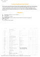

Chapter 3 - Instruction Set
Arithmetic and logic
Of all arithmetic operations, PIC like most microcontrollers supports only subtraction and addition.
Flags C, DC and Z are set depending on a result of addition or subtraction, but with one exception:
since subtraction is performed like addition of a negative value, C flag is inverse following a
subtraction. In other words, it is set if operation is possible, and reset if larger number was
subtracted from a smaller one.
Logic unit of PIC has capability of performing operations AND, OR, EX-OR, complementing (COMF)
and rotation (RLF and RRF).
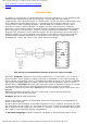
Instructions which rotate the register contents move bits inside a register through flag C by one
space to the left (toward bit 7), or to the right (toward bit 0). Bit which "comes out" of a register is
written in flag C, and value of C flag is written in a bit on the "opposite side" of the register.
Bit operations
Instructions BCF and BSF do setting or cleaning of one bit anywhere in the memory. Even though
this seems like a simple operation, it is executed so that CPU first reads the whole byte, changes
one bit in it and then writes in the entire byte at the same place.
Directing a program flow
Instructions GOTO, CALL and RETURN are executed the same way as on all other microcontrollers,
only stack is independent of internal RAM and limited to eight levels.
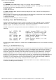
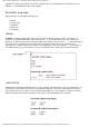
'RETLW k' instruction is identical with RETURN instruction, except that before coming back from a
subprogram a constant defined by instruction operand is written in W register. This instruction
enables us to design easily the Look-up tables (lists). Mostly we use them by determining data
position on our table adding it to the address at which the table begins, and then we read data from
that location (which is usually found in program memory).
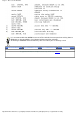
Table can be formed as a subprogram which consists of a series of 'RETLW k' instructions, where 'k'
constants are members of the table.
We write the position of a member of our table in W register, and using CALL instruction we call a
subprogram which creates the table. First subprogram line ADDWF PCL, f adds the position of a W
register member to the starting address of our table, found in PCL register, and so we get the real
data address in program memory. When returning from a subprogram we will have in W register the
contents of an addressed table member. In a previous example, constant 'k2' will be in W register
following a return from a subprogram.
RETFIE (RETurn From Interrupt - Interrupt Enable) is a return from interrupt routine and differs from
a RETURN only in that it automatically sets GIE (Global Interrupt Enable) bit. Upon an interrupt, this
bit is automatically cleared. As interrupt begins, only the value of program counter is put at the top
of a stack. No automatic storing of register values and status is provided.
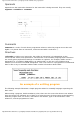
Conditional jumps are synthesized into two instructions: BTFSC and BTFSS. Depending on a bit
status in 'f' register that is being tested, instructions skip or don't skip over the next program
http://www.mikroelektronika.co.yu/english/product/books/PICbook/3_Poglavlje.htm (2 of 4) [4/2/2003 16:18:03]