
Information


© 2008 Microchip Technology Inc. DS39646C-page 101
PIC18F8722 FAMILY
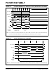
7.5.1 16-BIT BYTE WRITE MODE
Figure 7-1 shows an example of 16-bit Byte Write
mode for PIC18F8527/8622/8627/8722 devices. This
mode is used for two separate 8-bit memories con-
nected for 16-bit operation. This generally includes
basic EPROM and Flash devices. It allows table writes
to byte-wide external memories.
During a TBLWT instruction cycle, the TABLAT data is
presented on the upper and lower bytes of the
AD<15:0> bus. The appropriate WRH
or WRL control
line is strobed on the LSb of the TBLPTR.
FIGURE 7-1: 16-BIT BYTE WRITE MODE EXAMPLE
AD<7:0>
A<19:16>
(1)
ALE
D<15:8>
373
A<x:0>
D<7:0>
A<19:0>
A<x:0>
D<7:0>
373
OE
WRH
OE OE
WR
(2)
WR
(2)
CE
CE
Note 1: Upper-order address lines are used only for 20-bit address widths.
2: This signal only applies to table writes. See Section 6.1 “Table Reads and Table Writes”.
WRL
D<7:0>
(LSB)
(MSB)
PIC18F8X27/8X22
D<7:0>
AD<15:8>
Address Bus
Data Bus
Control Lines
CE