
User manual


Page 42
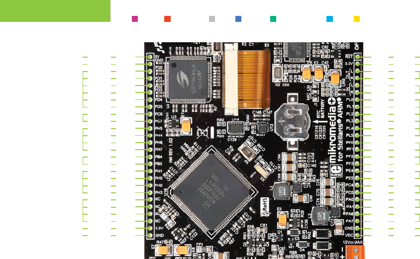
Many microcontroller pins are available for further connectivity via two 1x26 rows of connection pads on both
sides of the board. They are designed to match with mikromedia+ SHIELD for Stellaris
®
ARM
®
.
16. Pads
RST
3.3V
PL0
R
PL1
PL2
R
PL3
PL4
L
L
PL5
PF0
PF1
VDC
PF2
PF3
PE4
PE5
PC4
PC5
PA0
PA1
PA6
PA7
GND
27.
28.
33.
30.
34.
35.
32.
36.
37.
29.
31.
38.
39.
40.
52.
41.
42.
43.
44.
45.
46.
47.
48.
49.
50.
51.
Reset pin
3.3V pwr.
Audio out
Audio in
PWM lines
Interrupt lines
I2C2 lines
UART2 lines
UART1 lines
I2C1 lines
Ground
5-12V input
5V
GND
PD4
PD1
PD5
PC6
PD3
PC7
PH5
PD0
PD2
PH4
PH6
PH7
GND
PB4
PB5
PH1
PH0
PH2
PH3
NC
NC
NC
NC
3.3V
1.
2.
7.
4.
8.
9.
6.
10.
11.
3.
5.
12.
13.
14.
26.
15.
16.
17.
18.
19.
20.
21.
22.
23.
24.
25.
5V pwr.
Ground
Analog lines
UART3 lines
SPI2 lines
CAN lines
SPI1 lines
Not connected
3.3V pwr.
Ground
PWM Interrupt I2C UART Analog lines SPI CAN