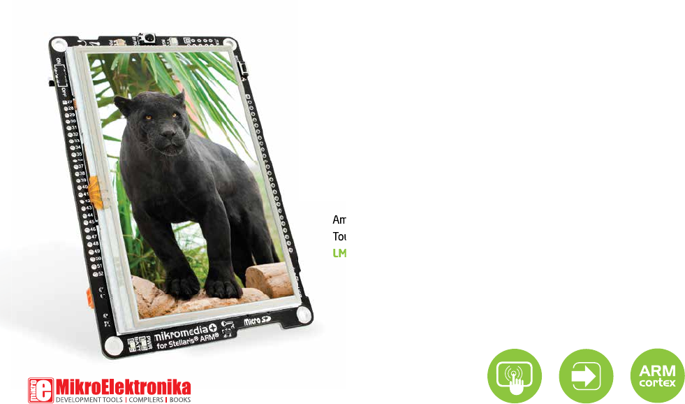
mikromedia+ for Stellaris® ARM® Amazingly compact, all-on-single-pcb development board carring 4.
TO OUR VALUED CUSTOMERS I want to express my thanks to you for being interested in our products and for having confidence in MikroElektronika. The primary aim of our company is to design and produce high quality electronic products and to constantly improve the performance thereof in order to better suit your needs. Nebojsa Matic General Manager The Stellaris®, ARM® and Windows® logos and product names are trademarks of Texas Instruments®, ARM® Holdings and Microsoft® in the U.S.A. and other countries.
Table of Contents Introduction to mikromedia+ for Stellaris® ARM® 4 4. RTC Battery and Reset Button 18 4 5. Crystal oscillator and 2.048V reference 20 Package Contains 5 6. MicroSD Card Slot 22 1. Power supply 6 7. Touch Screen 24 2. LM4F232H5QD microcontroller 8 8. Audio Module 26 Key microcontroller features 8 9. USB DEVICE connection 28 3. Programming the microcontroller 9 10. USB HOST connection 30 11.
Introduction to mikromedia+ for Stellaris® ARM® System Specification The mikromedia+ for Stellaris® ARM® is a compact development system with lots of on-board peripherals which allow development of devices with multimedia contents. The central part of the system is a 32-bit ARM® Cortex™-M4 power supply Via USB cable (5V DC) or via screw LM4F232H5QD 144-pin microcontroller. The mikromedia+ for Stellaris® ARM® features integrated modules such as stereo MP3 codec, 4.
L NA IO RE WA FT SO • • • • • • • • • • • • • • • • • • MIK ROC ILERS , MI COMP KRO BA SIC ,M IK RO PA SC AL • • • • • • • • • • • • • • • • • S VER DRI EXAM PLE S CO • PRODUCT DVD RS LE PI M AD DI T Package Contains www.mikroe.com www.libstock.
1. Power supply Figure 1-1: USB power supply Figure 1-2: Battery power supply Figure 1-3: Screw terminals power supply The mikromedia+ for Stellaris® ARM® board can be powered in three different ways: via USB connector using MINI-B USB cable provided with the board (CN4), via battery connector using Li-Polymer battery (CN5) or via screw terminals using laboratory power supply (CN3). After you plug in the appropriate power supply turn the power switch ON (SW1).
VCC-3.3V R38 10K R39 10K OC GND IN OUT 3 USB-VBUS_ER# Vusb_OUT 2 TPS2041B CN3 R42 D2 B340A R43 1K C71 100nF R45 10K C70 C66 C67 C68 C72 C79 22uF 22uF 22uF 1uF 100nF 10nF C140 C141 100pF 10pF V_INPUT E7 10uF USB-ID M1 DMP2160UW E8 10uF R46 D5 B340A 10K L3 1.5uH VCC-3.3V U9 Vbat_IN R49 1M LD1 M2 DMP2160UW BAT-VSENSE BAT-VSENSE VCC-3.3V R56 10K R57 1K L1 L2 VIN VOUT EN PGND FB PS GND PG VAUX VCC-3.
2. LM4F232H5QD microcontroller The mikromedia+ for Stellaris® ARM® development board comes with the 144-pin ARM® Cortex™-M4 LM4F232H5QD microcontroller. This high-performance 32-bit microcontroller with its integrated modules and in combination with other on-board modules is ideal for multimedia applications.
3.
Programming with mikroBootloader You can program the microcontroller with bootloader which is pre programmed into the device by default. To transfer .HEX file from a PC to MCU you need bootloader software (mikroBootloader USB HID) which can be downloaded from: http://www.mikroe.com/downloads/get/1976/mikromedia_plus_mikrobootloader_v210.zip step 1 – Connecting mikromedia 01 02 After software is downloaded unzip it to desired location and start mikroBootloader USB HID software.
step 2 – Browsing for .HEX file step 3 – Selecting .HEX file 01 0101 02 Figure 3-3: Browse for HEX Figure 3-4: Selecting HEX 01 Click the Browse for HEX button and from a pop-up window (Figure 3.4) choose the .HEX file that will be uploaded to MCU memory. 01 Select .HEX file using open dialog window. 02 Click the Open button.
step 4 – Uploading .HEX file 01 01 Figure 3-5: Begin uploading Figure 3-6: Progress bar 01 To start .HEX file uploading click the Begin uploading button. 01 You can monitor .
step 5 – Finish upload 01 01 Figure 3-7: Restarting MCU Figure 3-8: mikroBootloader ready for next job 01 Click the OK button after uploading is finished. Board will automatically reset and after 5 seconds your new program will execute.
Programming with mikroProg™ programmer Figure 3-9: mikroProg™ JTAG connector The microcontroller can be programmed with external mikroProg™ for Stellaris® programmer and mikroProg Suite™ for ARM® software. The external programmer is connected to the development system via JTAG connector, Figure 3-9. mikroProg™ is a fast USB 2.0 programmer with hardware Debugger support. It supports ARM® Cortex™-M3 and Cortex™-M4 microcontrollers from Stellaris®.
2 4 6 8 10 R85 10K JTAG-TMS JTAG-TCK JTAG-TDO JTAG-TDI RST# JTAG-TCK JTAG-TMS JTAG-TDI JTAG-TDO R84 10K 1 3 5 7 9 VCC-3.3V VCC-ADC VCC-3.
mikroProg Suite™ for ARM® software L NA IO RE WA FT SO • • • • • • • • • • • • • • • • • • MIK ROC ILERS , MI COMP KRO BA SIC ,M IK RO PA SC AL • • • • • • • • • • • • • • • • • S VER DRI EXAM PLE S CO • PRODUCT DVD RS LE PI M AD DI T mikroProg™ for Stellaris® programmer requires special programming software called mikroProg Suite™ for ARM®. This software is used for programming ALL of Stellaris® ARM® Cortex-M3™ and Cortex-M4™ microcontroller families.
Software installation wizard 01 Start Installation 02 Accept EULA and continue 03 Install for all users 04 Choose destination folder 05 Installation in progress 06 Finish installation Page 17
4. RTC Battery and Reset Button Reset Button The board is equipped with reset button, which is located on the front side of the board. If you want to reset the circuit, press the reset button. It will generate low voltage level on the microcontroller reset pin (input). A reset can also be externally provided through the pin 27 on the side headers. RTC Battery mikromedia+ for Stellaris® ARM® features an RTC battery holder for microcontroller RTC module.
VCC-CORE VCC-ADC VCC-3.3V VCC-3.3V R69 10K C115 100nF 100nF 100nF 100nF 100nF VCC-3.3V C116 C117 C118 C119 C120 100nF 100nF 100nF 100nF 100nF C121 C122 C124 C125 C126 100nF 100nF 1uF 1uF 1uF C127 C128 C129 C130 100nF 100nF 1uF 1uF C133 C134 C135 1uF 100nF 10nF VCC-3.3V VCC-CORE VCC-ADC VCC-3.
5. Crystal oscillator and 2.048V reference 01 03 The board is equipped with 01 16MHz crystal oscillator (X4) circuit that provides external clock waveform to the microcontroller OSC0 and OSC1 pins. This base frequency is suitable for further clock multipliers and ideal for generation of necessary USB clock, which ensures proper operation of bootloader and your custom USBbased applications. The board also contains 02 32.
VCC-CORE C111 C112 C113 C114 C115 100nF 100nF 100nF 100nF 100nF VCC-3.3V 144 143 142 141 140 139 138 137 136 135 134 133 132 131 130 129 128 127 126 125 124 123 122 121 120 119 118 117 116 115 114 113 112 111 110 109 VCC-ADC VCC-3.3V VCC-3.3V C118 C119 C120 100nF 100nF 100nF 100nF C121 C122 C124 C125 C126 100nF 100nF 1uF 1uF 1uF C127 C128 C129 C130 100nF 100nF 1uF 1uF VCC-3.3V VCC-CORE VREF VCC-ADC VCC-3.
6. microSD Card Slot 01 02 Board contains 01 microSD card slot for using 02 microSD cards in your projects. It enables you to store large amounts of data externally, thus saving microcontroller memory. microSD cards use Serial Peripheral Interface (SPI) for communication with the microcontroller. Ferrite and capcitor are provided to compensate the voltage and current glitch that can occur when pushing-in and pushingout microSD card into the socket.
C112 C113 C114 C115 100nF 100nF 100nF 100nF 100nF VCC-CORE C111 SD-CS# SD-CD# VCC-3.3V VCC-3.3V VCC-MMC FP3 FERRITE VCC-ADC C151 22uF VCC-3.3V VCC-MMC 144 143 142 141 140 139 138 137 136 135 134 133 132 131 130 129 128 127 126 125 124 123 122 121 120 119 118 117 116 115 114 113 112 111 110 109 VCC-3.3V C106 100nF VCC-3.
7. Touch Screen The development system features a 4.3‘‘ TFT 480x272 display covered with a resistive touch panel. Together they form a functional unit called a touch screen, Figure 7-1. It enables data to be entered and displayed at the same time. The TFT display is capable of showing graphics in 256K different colors.
FB 2 DZ1 MMSZ5246B 3 C1 100nF C4 C5 C6 C7 C8 C9 C10 C11 C12 C13 C14 C15 C16 C17 C18 C19 C20 1uF 1uF 1uF 1uF 1uF 1uF 1uF 1uF 1uF 1uF 1uF 1uF 1uF 1uF 1uF 1uF 1uF 1uF VCC-3.3V VCC-1.2V 1 2 VCC-3.3V C41 VCC-3.3V C22 C23 C24 C25 C26 C27 C28 C29 100nF 100nF 100nF 100nF 100nF 100nF 100nF 100nF 100nF C30 C31 C32 C33 C34 C35 C36 C37 2.
8. Audio Module Figure 8-1: On-board VS1053 MP3 codec 03 01 02 mikromedia+ for Stellaris® ARM® features stereo audio codec 01 VS1053. This module enables audio reproduction and sound recording by using 02 stereo headphones with microphone connected to the system via a 03 3.5mm connector CN2. All functions of this module are controlled by the microcontroller over Serial Peripheral Interface (SPI). IN and OUT channels are also provided on side headers.
E2 VCC-1.8V C138 100nF C63 100nF C58 100nF C64 100nF VCC-ADC C65 100nF E3 R15 470 R17 C44 1uF R20 R23 C46 C47 C48 E4 47nF 10nF 10nF 10uF SPI0-SCK SPI0-MOSI SPI0-MISO MP3-CS# MP3-RST# MP3-DREQ MP3-DCS 1 2 3 VCC-3.3V MICP MIC/LN-IN_L LN-IN_L R32 10K LN-IN_L C55 22pF X4 16MHz VCC-3.3V VCC-1.8V 1 C59 2.
9. USB DEVICE connection 01 02 Figure 9-1: Connecting USB cable to MINI-B USB connector ARM® Cortex™-M4 LM4F232H5QD microcontroller has integrated USB module, which enables you to implement USB communication functionality to your mikromedia board. Connection with target USB host is establish over 01 MINI-B USB connector. For proper insertion of the 02 MINI-B USB cable refer to Figure 9-1.
VCC-CORE VCC-3.3V VCC-ADC CN4 USB-VBUS X4 16MHz X5 32.
10. USB HOST connection 02 Figure 10-1: Connecting USB cable to MINI-B USB connector via USB adapter 01 mikromedia+ for Stellaris® ARM® can also be used as USB HOST which enables microcontroller to establish a connection with the target device (eg. USB keyboard, USB mouse, etc). The board provides necessary power supply to the target via TPS2041B IC. In order to enable the 01 USB HOST cable to be connected to the board, it is necessary to use the appropriate 02 MINI-B USB to USB type A adapter.
VCC-CORE VCC-3.3V VCC-ADC OC GND IN OUT USB-VBUS_ER# 2 1 TPS2041B C136 100nF D3 PMEG3010ER CN4 USB MINIB 1 2 3 4 5 U18 Vusb_OUT E9 10uF VBUS DD+ ID GND C114 C115 100nF 100nF 100nF C116 C117 C118 C119 C120 100nF 100nF 100nF 100nF 100nF C121 C122 C124 C125 C126 100nF 100nF 1uF 1uF 1uF C127 C128 C129 C130 100nF 100nF 1uF 1uF FP5 USB-D_N USB-D_P USB-ID E7 10uF E8 10uF R47 1K USB-VBUS X4 16MHz C133 C134 C135 1uF 100nF 10nF X5 32.768KHz VCC-3.
11. Accelerometer On board ADXL345 accelerometer is used to measure acceleration in three axis: x, y and z. The accelerometer function is defined by the user in the program loaded into the microcontroller. Communication between the accelerometer and the microcontroller is performed via the I2C interface.
VCC-3.3V VCC-3.3V I2C0-SDA OSC1 OSC0 C109 10pF XOSC1 GNDX XOSC0 C110 10pF VCC-3.3V C139 100nF C98 100nF 1 2 3 4 5 6 7 8 9 10 11 12 13 14 15 16 17 18 19 20 21 22 23 24 25 26 27 28 29 30 31 32 33 34 35 36 PD7 PD6 PD5 PD4 PE5 PE4 GND VDD PB4 PB5 PE7 PE6 PP1 PP0 PJ7 PJ6 PJ5 PJ4 VDDC GND VDD PJ3 PJ2 PJ1 PJ0 PN3 SWCLK/TCK/PC0 SWDIO/TMS/PC1 TDI/PC2 SWO/TDO/PC3 GND VDD PK4 PK5 PK6 PK7 U18 C108 22pF VCC-3.
12. Flash Memory Figure 12-1: Flash memory module Since multimedia applications are getting increasingly demanding, it is necessary to provide additional memory space to be used for storing more data. The flash memory module enables the microcontroller to use additional 8Mbit flash memory. It is connected to the microcontroller via the Serial Peripheral Interface (SPI).
VCC-CORE VCC-3.3V VCC-3.3V VCC-ADC VCC-3.3V VCC-3.3 V X4 16MHz X5 32.
13. RF Transceiver Figure 13-1: RF transceiver antenna Figure 13-2: RF transceiver module mikromedia+ for Stellaris® ARM® board features RF transceiver chip with 2.4GHz chip antenna. It is suitable for wireless operation in the world wide ISM frequency band at 2.400 - 2.4835 GHz with air data rate up to 2Mbps. RF transceiver module is connected to the microcontroller via the Serial Peripheral Interface (SPI).
VCC-CORE VCC-3.3V OSC1 OSC0 VCC-3.
14. Buzzer The board is also equipped with piezo buzzer. It is an electric component which can be used to create sound waves when provided with electrical signal. Microcontroller can create sound by generating a PWM signal. Frequency of the signal determines the pitch of the sound and duty cycle of the signal can be used to increase or decrease the volume.
VCC-CORE VCC-CORE R1 R2 C114 C115 100nF 100nF 100nF C116 C117 C118 C119 C120 100nF 100nF 100nF 100nF 100nF C121 C122 C124 C125 C126 100nF 100nF 1uF 1uF 1uF C127 C128 C129 C130 100nF 100nF 1uF 1uF C133 C134 C135 1uF 100nF 10nF VCC-3.3V OSC1 OSC0 OSC1 OSC0 VBAT XOSC1 GNDX XOSC0 SC1 DX SC0 BAT1 3000TR Figure 14-2: Buzzer module schematic Page 39 C113 100nF VCC-3.
15. Other modules 03 02 04 01 The board also contains additional peripherals that can be very useful, such as 01 PIN photodiode, 02 IR receiver, 03 RGB led diode and 04 analog temperature sensor. PIN photodiode is a type of photo detector capable of converting light into the voltage with high sensitivity and speed of response. It is connected to the microcontroller analog pin. IR receiver is used for infrared remote control systems.
VCC-CORE LD3 C130 1uF 1uF VCC-3.3V U16 VCC-3.3V 4 3 2 1 IR_RX C100 4.7uF TSOP6238 C116 C117 C118 C119 C120 100nF 100nF 100nF 100nF 100nF VCC-3.3V X4 16MHz C111 C112 C113 C114 C115 100nF 100nF 100nF 100nF 100nF VCC-3.3V FP4 C134 C135 1uF 100nF 10nF X5 32.
16. Pads 5V pwr. Ground Analog lines UART3 lines SPI2 lines CAN lines SPI1 lines Not connected 3.3V pwr. Ground 5V GND PD0 PD1 PD2 PD3 PD4 PD5 PC6 PC7 PH5 PH4 PH6 PH7 PB4 PB5 PH1 PH0 PH2 PH3 NC NC NC NC 3.3V GND PWM Interrupt I2C UART 1. 2. 3. 4. 5. 6. 7. 8. 9. 10. 11. 12. 13. 14. 15. 16. 17. 18. 19. 20. 21. 22. 23. 24. 25. 26. Analog lines SPI CAN 27. 28. 29. 30. 31. 32. 33. 34. 35. 36. 37. 38. 39. 40. 41. 42. 43. 44. 45. 46. 47. 48. 49. 50. 51. 52. RST 3.
C130 100nF 100nF 1uF 1uF VCC-ADC VCC-3.3V VCC-CORE C129 HDR-CAN_RX HDR-CAN_TX C128 C121 C122 C124 C125 C126 100nF 100nF 1uF 1uF 1uF C133 C134 C135 1uF 100nF 10nF VCC-3.
17. mikromedia+ accessories 07 02 04 03 01 05 05 05 08 08 05 06 07 Figure 17-1: mikromedia+ shield Page 44 We have prepared an extension board pin-compatible with your mikromedia+ board, which enables you to easily expand your basic board functionality. It is called mikromedia+ SHIELD for Stellaris® ARM®.
VCC-3.3V VCC-5V PD0/AN1 PD4 PD5 PH0/SPI-SCK PH2/SPI-MISO PH3/SPI-MOSI AN RST CS SCK MISO MOSI 3.3V GND 1 VCC-3.3V PL0/PWM1 PF0/INT1 PA0/UART1-RX PA1/UART1-TX PE4/I2C-SCL PE5/I2C-SDA PWM INT RX TX SCL SDA 5V GND PD1/AN2 PC6 PC7 PH0/SPI-SCK PH2/SPI-MISO PH3/SPI-MOSI VCC-5V PD0/AN1 PD1/AN2 PD2/AN3 PD3/AN4 PD4 PD5 PC6 PC7 PH5 PB4/CAN-RX PB5/CAN-TX PH1 PH0/SPI-SCK PH2/SPI-MISO PH3/SPI-MOSI VCC-3.3V VCC-5V AN RST CS SCK MISO MOSI 3.3V GND 2 VCC-3.
What’s next? You have now completed the journey through each and every feature of mikromedia+ for Stellaris® ARM® board. You got to know it’s modules and organization. Now you are ready to start using your new board. We are suggesting several steps which are probably the best way to begin. We invite you to join the users of mikromedia™ brand. You will find very useful projects and tutorials and can get help from a large ecosystem of users.
DISCLAIMER All the products owned by MikroElektronika are protected by copyright law and international copyright treaty. Therefore, this manual is to be treated as any other copyright material. No part of this manual, including product and software described herein, may be reproduced, stored in a retrieval system, translated or transmitted in any form or by any means, without the prior written permission of MikroElektronika.
If you want to learn more about our products, please visit our website at www.mikroe.com If you are experiencing some problems with any of our products or just need additional information, please place your ticket at www.mikroe.com/esupport If you have any questions, comments or business proposals, do not hesitate to contact us at office@mikroe.com mikromedia Plus for Stellaris® ARM® Manual ver. 1.