
Information


DocID022152 Rev 4 103/185
STM32F405xx, STM32F407xx Electrical characteristics
Equation 2
Equation 2 allows to calculate the increment step (INCSTEP):
f
VCO_OUT
must be expressed in MHz.
With a modulation depth (md) = ±2 % (4 % peak to peak), and PLLN = 240 (in MHz):
An amplitude quantization error may be generated because the linear modulation profile is
obtained by taking the quantized values (rounded to the nearest integer) of MODPER and
INCSTEP. As a result, the achieved modulation depth is quantized. The percentage
quantized modulation depth is given by the following formula:
As a result:
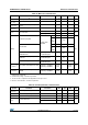
Figure 35 and Figure 36 show the main PLL output clock waveforms in center spread and
down spread modes, where:
F0 is f
PLL_OUT
nominal.
T
mode
is the modulation period.
md is the modulation depth.
Figure 35. PLL output clock waveforms in center spread mode
INCSTEP round 2
15
1–()md PLLN××()100 5× MODEPER×()⁄[]=
INCSTEP round 2
15
1–()2 240××()100 5× 250×()⁄[]126md(quantitazed)%==
md
quantized
% MODEPER INCSTEP× 100× 5×()2
15
1–()PLLN×()⁄=
md
quantized
%250126× 100× 5×()2
15
1–()240×()⁄ 2.002%(peak)==
Frequency (PLL_OUT)
Time
F0
tmode
md
ai17291
md
2 x tmode