
Information


Electrical characteristics STM32F20xxx
110/178 DocID15818 Rev 11
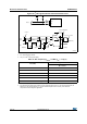
Figure 40. I
2
C bus AC waveforms and measurement circuit
1. R
S
= series protection resistor.
2. R
P
= external pull-up resistor.
3. V
DD_I2C
is the I
2
C bus power supply.
Table 53. SCL frequency (f
PCLK1
= 30 MHz.,V
DD
= 3.3 V)
(1)(2)
1. R
P
= External pull-up resistance, f
SCL
= I
2
C speed,
2. For speeds around 200 kHz, the tolerance on the achieved speed is of ±5%. For other speed ranges, the
tolerance on the achieved speed ±2%. These variations depend on the accuracy of the external
components used to design the application.
f
SCL
(kHz)
I2C_CCR value
R
P
= 4.7 kΩ
400 0x8019
300 0x8021
200 0x8032
100 0x0096
50 0x012C
20 0x02EE
ai14979c
START
SDA
R
P
I²C bus
V
DD_I2C
STM32Fxx
SDA
SCL
t
f(SDA)
t
r(SDA)
SCL
t
h(STA)
t
w(SCLH)
t
w(SCLL)
t
su(SDA)
t
r(SCL)
t
f(SCL)
t
h(SDA)
S T AR T REPEATED
START
t
su(STA)
t
su(STO)
STOP
t
w(STO:STA)
V
DD_I2C
R
P
R
S
R
S