
Installation manual

27
Troubleshooting Guide
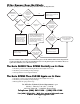
If your gate opener does not function properly after it is installed, use this guide before calling the
GTO Service Department.
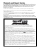
Routinely grease the gate hinges at least 4 times a year; more frequently if the gate is near a coastal area. Spray push pull tube
with a high quality silicon and wipe clean regularly and replace the battery every two (2) years.
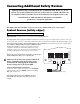
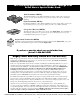
LEDs Indicators Diagnostic:
GREEN: AC power indicator.
a. ON: 18 Vac power is present. This
LED will be on regardless of the ON/
OFF switch position.
b. OFF: No AC power is present. The
battery will not be charged. The
operator may still operate, however
AC power should be restored as soon
as possible.
RED: Charging indicator. This LED will cycle
ON and OFF as it trickle charges the battery
under normal operation.
YELLOW: RF receiver signal indicator. Blinking
on/off as RF signal is received. This LED is typically blinking under normal operation.
a. ON: RF signal (318 MHz) is received.
b. OFF: RF signal (318 MHz) is NOT received.
WHITE: Activity/status indicator. (Normally OFF)
a. This LED will blink once whenever there is a change at any of the inputs.
EDGE
RED
BLK
GREEN
SAFETY
CYCLE
RADIO
18 VAC
INPUT
LEARN
TRANSMITTER
SET
CLOSE
LIMIT
COMMON
RED LED
GREEN LED
WHITE LED
YELLOW LED
15 AMP
FINAL STEP
Installation is Complete
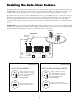
Replace control board access cover. If you were working with the opener with the control board
access facing up, remove the opener arm from both mounts and remount it in the upright
position. Failure to remount opener in the up right position will cause damage to the opener.
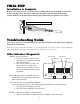
Gate Opener in the upright position
®
E
-Z
G
A
T
E
O
P
E
N
E
R
250
UL
32
5 SE
RIES
C
a
n
C
a
us
e
In
jury
o
r D
ea
th
M
O
V
IN
G
G
A
T
E
L
I
S
T
E
D
®
U
S