
Installation manual

26
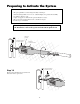
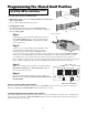
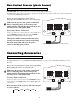
Connecting Accessories
The Mighty Mule 250 can accept NORMALLY OPEN CONTACT accessories, such as; Push Button Entry Devices and
Key Pads.
Refer to the sensor manufacturer’s instructions for information
about installing these devices on a vehicular gate.
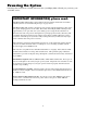
Make sure the power to the opener is turned off
before connecting safety device wiring to the
terminal blocks. Unplugging the transformer does
not turn power to the opener OFF.
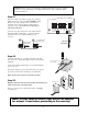
Accessory Input Connection:
Connect one of the accessory wires to the COMMON terminal
and the other to the CYCLE terminal on the Mighty Mule 250
control board.
Wire from Accessory
EDGE
RED
BLK
GREEN
SAFETY
CYCLE
RADIO
18 VAC
INPUT
LEARN
TRANSMITTER
SET
CLOSE
LIMIT
COMMON
15 AMP
Each activation of the accessory will cause the gate
to cycle as follows:
OPEN STOP CLOSE STOP
If not connecting accessories skip to next section.
Refer to the sensor manufacturer’s instructions for
information about installing these devices on a vehicular gate.
Make sure the power to the opener is turned off
before connecting safety device wiring to the
terminal blocks. Unplugging the transformer does
not turn power to the opener OFF.
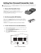
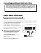
Non-Contact Sensor Connection:
Connect one of the non-contact sensor dry contact output wires
to the COMMON terminal and the other to the SAFETY
terminal on the Mighty Mule 250 control board.
This input is ONLY monitored when the gate is
closing. Activating the non-contact (obstructing
the safety beam path) will cause the gate to
reverse to the fully open position.
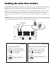
Non-Contact Sensors (photo beams)
The Mighty Mule 250 can also accept "Safety" input from normally open "dry-contact" output devices such as safety beams
connected to the SAFETY input terminal.
Output Wire from Non-Contact Sensor (photo beam)
EDGE
RED
BLK
GREEN
SAFETY
CYCLE
RADIO
18 VAC
INPUT
LEARN
TRANSMITTER
SET
CLOSE
LIMIT
COMMON
15 AMP
If not installing a non-contact sensor skip to next section.
PLEASE NOTE: Non-contact sensors are not included with the Mighty Mule 250.