
Installation manual


11
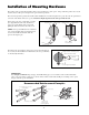
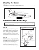
Horizontal Cross Member
Gate Swings Evenly and Freely
Hung Firmly and Plumb
Receiver
Post Bracket Assembly
Gate Bracket
Single Gate Opener
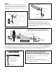
Fence Post Set in Concrete
Low Voltage Wire from Transformer
Closed Position
Positive Stop Plate
Warning Sign
Contact Sensor
recommended but not included
Contact Sensor
recommended but not included
GTO indoor
Transformer
(surge protector
not supplied)
®
E
-Z
G
A
T
E
O
P
E
N
ER
2
50
S
E
R
I
E
S
Can Cause Injury or Death
M
O
V
I
N
G
G
A
T
E
L
I
S
T
E
D
®
U
S
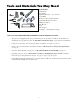
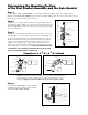
Preparation of the Gate
Step 1
The gate must be plumb, level, and swing freely on its
hinges. Wheels must not be attached to the gate. The
gate must move throughout its arc without binding or
dragging on the ground. Note that gates over 200 lb.
should have ball bearing hinges with grease fittings.
Step 2
The fence post must be secured in the ground with
concrete so it will not twist or flex when the opener is
activated. To prevent accelerated wear and tear of the
gate hardware and gate opener, be sure to position the
opener near the centerline of the gate. The addition of
a horizontal or vertical cross member (if one is not
already in place) to provide a stable area for mounting
the gate bracket is also important.
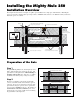
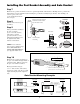
Installation Overview
The diagram shown below is an example of a pull-to-open installation on a single gate chain link fence. Mounting the
opener on a masonry column requires special procedures; call GTO Technical Service at 1-800-543-1236 if you intend to
mount the opener on a column.
Horizontal Cross Member
Vertical Cross Member with
Horizontal Cross Member
C
L
C
L
Installing the Mighty Mule 250