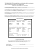
Installation Manual for the ® E-Z GATE OPENER 250 UL325 SERIES ¨ ™ 1-800-543-GATE (4283) • www.mightymule.com LIS TED 75 Automatic Gate Opener System for Single Swing Gates Only WARNING! This equipment is similar to other gate or door equipment and meets or exceeds Underwriters Laboratory Standard 325 (UL 325).
The Mighty Mule 250 is intended for use with single vehicular swing gates and is classified to be used in Class I applications. VEHICULAR GATE OPENER CLASS CATEGORIES Residential Vehicular Gate Opener-Class I: A vehicular gate opener (or system) intended for use in a home of one-to-four single family dwelling, or a garage or parking area associated therewith.
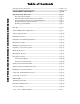
Table of Contents KEEP THESE INSTRUCTIONS FOR FUTURE REFERENCE Gate Opener Class Categories -------------------------------------------------------------inside cover Units and Standards Conversion Chart ---------------------------------------------------inside cover PLEASE READ THIS FIRST! ------------------------------------------------- page iii Important Safety Instructions -----------------------------------------------------------page 1 Disconnecting the Opener ---------------------------------------
® E-Z GATE OPENER 250 UL325 SERIES ™ 1-800-543-GATE (4283) • www.mightymule.com PLEASE READ THIS FIRST! Thank you for purchasing a Mighty Mule 250—GTO's "do-it-yourself" automatic single gate swing opener! When correctly installed and properly used, your Mighty Mule 250 will give you many years of reliable service.
IMPORTANT SAFETY INSTRUCTIONS Automatic gate openers produce high levels of force. Consumers should understand and inform all users of the potential hazards associated with improperly designed, installed, and maintained gate opener systems. Keep in mind that the gate opener is just one component of the total gate operating system. Each component must work in unison to provide the consumer with convenience, security, and safety. This manual contains various safety precautions and warnings for the consumer.
IMPORTANT SAFETY INSTRUCTIONS For The Consumer WARNING: To reduce the risk of injury or death: 1. READ AND FOLLOW ALL INSTRUCTIONS. Failure to meet the requirements set forth in the instruction manual could cause severe injury and/or death, for which the manufacturer cannot be held responsible. 2. When designing a system that will be entered from a highway or main thoroughfare, make sure the system is placed far enough from the road to prevent traffic congestion. 3.
IMPORTANT SAFETY INSTRUCTIONS II. During Installation 1. Install the gate opener on the inside of the property and fence line. DO NOT install an opener on the outside of the gate where the public has access to it. 2. Be careful with moving parts and avoid close proximity to areas where fingers or hands could be pinched. 3. Devices such as safety edges and photo beams provide additional protection against entrapment (see page 5). 4.
IMPORTANT SAFETY INSTRUCTIONS III. After Installation 1. Attach the warning signs (included) to each side of the gate to alert the public of automatic gate operation. It is your responsibility to post warning signs on both sides of your gate. If any of these signs or warning decals become damaged, illegible or missing, replace them immediately. Contact GTO for free replacements. 2. The gate is automatic and could move at any time, posing a serious risk of entrapment.
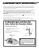
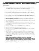
IMPORTANT SAFETY INSTRUCTIONS Secondary Means of Protection Against Entrapment As specified by Gate Operator Safety Standard, UL 325 (30A.1.1), automatic gate openers shall have provisions for, or be supplied with, at least one independent primary and one independent secondary means to protect against entrapment. The Mighty Mule 250 utilizes Type A, an inherent (i.e., built-in) entrapment sensing system as the primary type of entrapment protection.
IMPORTANT SAFETY INSTRUCTIONS Required Safety Precautions for Gates Install Warning Signs Warning signs included alert people of automatic gate operation and are required when installing the Mighty Mule 250. Furthermore, a walk-through gate must be installed if pedestrian traffic is expected near the vehicular gate. We recommend using the Bulldog Pedestrian Gate Lock (Call the GTO Sales Department at 1-800-543-4283) for controlled access.
IMPORTANT SAFETY INSTRUCTIONS These warning labels should be placed at the locations specified below. If any of them are missing, immediately contact GTO for free replacements at 1-800-543-4283. ! WARNING UL325 SERIES ™ Logo and warning labels (2) installed on each side of opener housing Moving Gate Can Cause Injury Or Death (113.4 kg) (3.7 m) 1. KEEP CLEAR! Gate may move at any time. 2. Do not allow children to operate gate or play in gate area. 3. This gate is for vehicles only.
Gate Opener Parts List Opener and Mounting Hardware 4 1/2" x 4 1/2" Setback Template (1) ® E E-Z GAT ly Assemb Bracket ual Post tion Man of the allation the Installa See Inst and 6 in 5 pages Transformer (1) R Customer Support Card (1) Extra 15 Amp Fuse (1) Gate Opener (1) ¨ 75 LISTED ® 250 IES 25 SER UL3 ENER TE OP E-Z GA Gate Bracket (1) E GAT Death NG ury or MOVI use Can Ca ! WARNING Closed Position Stop Plate (1) Post Bracket (2) Inj GTO Transmitter (1) Moving Gate Can Cause Inju
Tools and Materials You May Need Tools Needed • Safety Glasses • Power Drill • Open End Wrenches — 7/16" and 9/16" • 3/8" Drill Bit • Hacksaw or Heavy Duty Bolt Cutters • Slotted (Flat Bladed) Screwdriver • Phillips Screwdriver • Tape Measure • Level • Wire Strippers • C-Clamps — small, medium, and large ALSO, YOU WILL NEED THESE ITEMS BEFORE YOU BEGIN THE INSTALLATION • The gate needs a stop post for the open position. This post is not provided.
Technical Specifications MIGHTY MULE 250 DRIVE • Low friction screw drive (linear actuator) rated for -5 ºF to +160 ºF (-19 ºC to +88.8 ºC). • Powered by a 12 Vdc motor with integral case hardened steel gear reducer. Motor speed reduced to 270 rpm. • Maximum opening arc of 110º. Approximate 90º opening time is 18 to 20 seconds, depending on weight of gate. POWER • 12 Volt, 1.2 Amp hour sealed lead acid battery. The charging circuit built in to the Mighty Mule 250 is designed for the GTO battery.
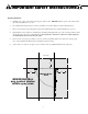
Installing the Mighty Mule 250 Installation Overview The diagram shown below is an example of a pull-to-open installation on a single gate chain link fence. Mounting the opener on a masonry column requires special procedures; call GTO Technical Service at 1-800-543-1236 if you intend to mount the opener on a column.
Installation of Mounting Hardware The position of the post bracket determines the leverage and efficiency of the opener. The post bracket position also sets the clearance between the opener and gate in the open and closed positions. The curved design of the post bracket works well for installations on round and square fence posts. Because the post bracket carries the entire thrust of the active opener, bolts that completely penetrate the fence post must be used.
Determining the Mounting Position of the Post Bracket Assembly and the Gate Bracket Step 3 Study the 4 1/2" x 4 1/2" setback template (see insert) provided with this manual. Once you are familiar with its illustrations, cut and save the template from the insert. The template will determine the correct position of the post pivot bracket before mounting the opener on the fence post.
Step 7 Front Mount Attach the gate bracket to the front mount of the opener using a clevis pin, washer and hairpin clip. Now attach the rear mount of the opener to the post pivot bracket, that is clamped to the fence post, using the clevis pin washer and hairpin clip. Clevis Pin Clevis Pin Gate Bracket Rear Mount Washer Hairpin Clip Opener Washer With the gate in the open position (80º to 110º from its closed position), adjust the post bracket assembly and gate bracket until the opener is level.
Installing the Post Bracket Assembly and Gate Bracket Step 7 Mark reference points for bolt holes on the fence post through middle of bracket slots. Marking reference points in this manner allows room for adjustment when mounting the post bracket assembly and gate bracket. After marking your reference points, remove the opener and brackets from the fence and gate. EXAMPLES Mark fence post through TOP VIEW middle of bracket slots Step 8 and drill 3/8" holes Drill 3/8" holes into fence post as marked.
Mounting the Opener Step 11 Attach the opener to the securely bolted post bracket assembly and gate bracket using clevis pins, washers, and hairpin clips. Verify that the opener is level and adjust the post bracket assembly if necessary.
Preparing to Activate the System Check List • The gate is plumb, level, and swings smoothly on its hinges. • After measuring with the 4 1/2" x 4 1/2" setback template, the post bracket assembly was bolted to the fence post. • A plate or support was added for the gate bracket (if necessary). • The opener is level and mounted on the centerline of the gate. • Positive stops are installed.
Wiring the Receiver Step 15 COMMON CYCLE EDGE RADIO SAFETY RED 18 VAC INPUT SET CLOSE LIMIT BLACK RED Insert wire into terminal block. GREEN Close and lock wire in place. BLK GREEN 2 1 15 AMP The receiver wire has three leads. Connect the RED, BLACK and GREEN leads to the RADIO TERMINAL BLOCK on the control board. Insert each wire into its corresponding terminal block and secure the wires by pressing down on the white terminal block tabs until they lock in place. (shown below).
Powering the System Following these instructions carefully will assure that your Mighty Mule 250 will give you many years of reliable service. IMPORTANT INFORMATION, please read: The Mighty Mule 250 E-Z Gate Opener will not function until the transformer is installed and the system is activated following the steps on pages 20-22. The Mighty Mule 250 circuitry is designed to only operate with the transformer connected to the opener and plugged into an AC outlet.
Connecting the Battery Battery Access Panel Step 17 Remove the Battery Access Panel on the bottom of the opener arm. O N O F F VING Can Ca use Inj GA ury or TE Death MO UL325 ER E-Z GA TE OP EN LIS TED ® SERIE S 250 Step 18 US ® Make sure the opener power switch is in the OFF position. Connect the RED battery wire to the POSITIVE (+) terminal on the battery. The BLACK wire should already be connected to the NEGATIVE (–) terminal from the factory. Replace the Battery Access Cover.
IMPORTANT: The charging circuit built in to the Mighty Mule 250 is designed for the GTO battery. To avoid possible damage to the Mighty Mule 250 or the battery, ONLY use GTO replacement batteries. Step 21 15 AMP Strip 3/16" off the ends of the low voltage wire and twist tightly. Insert these ends to the 18 VAC INPUT terminal block located on the control board (see illustration at right). The wires can be inserted into either terminal regardless of color.
Programming the Closed Limit Position Transformer MUST be plugged in before proceeding with this next section. Fully Open Position Your Mighty Mule 250 has two Limit Settings 1) OPEN Limit setting: (Gate in the OPEN POSITION / FACTORY SET & NOT ADJUSTABLE) The open limit setting is the fully open position.
Setting Your Personal Transmitter Code All GTO transmitters are set to a standard code at the factory and are ready to operate your Mighty Mule 250. For your safety and security, however, we strongly recommend that you replace the factory setting with your own personal code. Follow the directions below: 1. Remove the Transmitter Cover Grasp the sides of the access cover and slide it away from the transmitter button (see illustration).
Enabling the Auto-Close Feature The Mighty Mule 250 is equipped with a built-in auto-close feature option. The auto-close feature will automatically activate the Mighty Mule 250 and close the gate if it is left at the open position more than 60 seconds. The auto-close feature comes disabled from the factory, allowing the gate to remain open until activated by a transmitter, push button or keypad.
Connecting Additional Safety Devices Although GTO strongly recommends the use of additional safety devices, we do not endorse any specific brand names. Only use products that are certified and listed to be in compliance with UL (United Laboratories) and national and regional safety codes. Call GTO Sales at 1-800-543-4283 for information on compatible products for your specific application. The Mighty Mule 250 will ONLY accept accessory devices with normally open contact output.
Non-Contact Sensors (photo beams) If not installing a non-contact sensor skip to next section. PLEASE NOTE: Non-contact sensors are not included with the Mighty Mule 250. The Mighty Mule 250 can also accept "Safety" input from normally open "dry-contact" output devices such as safety beams connected to the SAFETY input terminal. Refer to the sensor manufacturer’s instructions for information about installing these devices on a vehicular gate.
FINAL STEP Installation is Complete Replace control board access cover. If you were working with the opener with the control board access facing up, remove the opener arm from both mounts and remount it in the upright position. Failure to remount opener in the up right position will cause damage to the opener.
If the Opener Does Not Work: Be sure the opener power switch is in the ON position then follow the diagram below. Start here: Is the transformer plugged in and AC power present at the outlet? NO Is the Green LED light on? Restore AC power to the opener and allow at least 1 hour for the battery to recharge. NO NO YES YES Is the 15 AMP fuse blown? NO YES YES YES Replace the 15 AMP fuse. Never replace with a higher AMP rated fuse.
Warranty and Repair Service If your Mighty Mule 250 is not operating properly, DO NOT RETURN to the store. First try the TROUBLE SHOOTING GUIDE beginning on page 27. If that doesn't help, call GTO's Service Department at 1-800-543-1236, or (850)575-4144 and we will be glad to help you solve any problems you may still have. You will need the serial number (located on the control box cover) and date of purchase when calling for assistance.
Accessory Catalog These Accessories are Available From Your Retail Store GTO Digital Keypad (FM137) The specially designed digital keypad can easily be installed as a wireless or wired keypad. It can be programmed to use up to fifteen different personal identification number (PIN) codes. Each code is face programmable with additional security features built in. Requires 3 AA batteries (not included).
The Following Accessories Are Available Through Your Retail Store's Special Order Desk. Dual Transmitter (RB742) The Dual Transmitter is a two button transmitter for remote control of two separate gate openers, or a gate opener and garage door opener (see Garage Door Receiver). Battery included. Triple Transmitter (RB743) The Triple Transmitter is a three button transmitter for remote control of three separate gate openers and/or garage door openers (see Garage Door Receiver). Battery included.
Installation Check List This operator conforms to CLASS I applications. The installer verifies that: ____ WARNING SIGNS are securely installed, one on each side of the gate panel. ____ Non-contact sensors (photo beams) are installed, one across each side of the gate opening. ____ Contact sensors (safety edges) are installed and are functional at all hazard or pinch points. ____ Hard wired contact sensors are located and wired to avoid any mechanical damage.
Extended Warranty for Mighty Mule 250 E-Z Gate Opener $50.00 within 90 days — for a one (1) Year Extended Warranty $75.00 within 90 days — for a two (2) Year Extended Warranty ® Mighty Mule 250 E-Z Gate Opener Limited Warranty E-Z GATE OPENERS An EXTENDED WARRANTY is now available for Mighty Mule 250 E-Z Gate openers. The Warranty will provide an additional ONE (1) or TWO (2) Year Limited Warranty after the original ONE (1) Year Limited Mighty Mule 250 Warranty you received with your original purchase.