Installation Manual for the AUTOMATIC GATE OPENER Automatic Gate Opener System FOR DUAL SWING GATES WARNING! RB928 This product meets and exceeds the requirements of UL 325, the standard which regulates gate opener safety, as established and made effective March 1, 2000, by Underwriters Laboratories Inc. rev - 07/30/01 READ ALL INSTRUCTIONS CAREFULLY AND COMPLETELY before attempting to install and use this automatic gate opener. This gate opener produces a high level of force.
The Mighty Mule Gate Opener® is intended for use with vehicular swing gates. The opener can be used in Class I, Class II and Class III applications. VEHICULAR GATE OPENER CLASS CATEGORIES Residential Vehicular Gate Opener-Class I: A vehicular gate opener (or system) intended for use in a home of one-to-four single family dwelling, or a garage or parking area associated therewith.
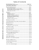
Table of Contents Gate Opener Class Categories ---------------------------------------------- inside cover Units and Standards Conversion Chart ------------------------------------ inside cover PLEASE READ THIS FIRST! ------------------------------------------------- page iii KEEP THESE INSTRUCTIONS FOR FUTURE REFERENCE Important Safety Instructions -------------------------------------------------Disconnecting the Opener ---------------------------------------------------Important Safety Instructions for
AUTOMATIC GATE OPENER PLEASE READ THIS FIRST! Thank you for purchasing a Mighty Mule Gate Opener®—GTO's "do-it-yourself" automatic gate opener! When correctly installed and properly used, your Mighty Mule Gate Opener® will give you many years of reliable service. Please read the following information and watch the enclosed videotape to ensure you have the correct system for your particular needs. Furthermore, this manual and the videotape will enable you to properly install your Mighty Mule Gate Opener®.
IMPORTANT SAFETY INSTRUCTIONS Because automatic gate openers produce high levels of force, consumers need to know the potential hazards associated with improperly designed, installed, and maintained gate opener systems. Keep in mind that the gate opener is just one component of the total gate operating system. Each component must work in unison to provide the consumer with convenience, security, and safety. This manual contains various safety precautions and warnings for the consumer.
IMPORTANT SAFETY INSTRUCTIONS For The Consumer WARNING: To reduce the risk of injury or death: 1. READ AND FOLLOW ALL INSTRUCTIONS. 2. When designing a system that will be entered from a highway or main thoroughfare, make sure the system is placed far enough from the road to prevent traffic congestion. 3. The gate must be installed in a location that provides adequate clearance between it and adjacent structures when opening and closing to reduce the risk of entrapment.
IMPORTANT SAFETY INSTRUCTIONS III. After Installation 1. Attach the warning signs (included) to both sides of each gate leaf to alert the public of automatic gate operation. It is your responsibility to post warning signs on both sides of your gates. If any of these signs or warning decals become damaged, illegible or missing, replace them immediately. Contact GTO for replacements. 2. Do not allow children or pets near your gate. Never let children operate or play with gate controls.
IMPORTANT SAFETY INSTRUCTIONS Secondary Means of Protection Against Entrapment As specified by Underwriters Laboratories Inc. UL 325 (30A.1.1), automatic gate openers shall have provisions for, or be supplied with, at least one independent primary and one independent secondary means to protect against entrapment. The Mighty Mule Gate Opener® utilizes Type A, an inherent (i.e., built-in) entrapment sensing system, as the primary type of entrapment protection.
IMPORTANT SAFETY INSTRUCTIONS Required Safety Precautions for Dual Gates Install Warning Signs Warning signs alert people of automatic gate operation and are required when installing the Mighty Mule Gate Opener®. Furthermore, a walk-through gate must be installed if pedestrian traffic is expected near the vehicular gate. We recommend using the GTO Bulldog Pedestrian Gate Lock (Call the GTO Sales Department) for controlled access.
IMPORTANT SAFETY INSTRUCTIONS These warning labels should be found at the locations specified below. If any of them are missing, immediately contact GTO for replacements. ! ! WARNING WARNING MOVING GATE Can Cause Injury or Death 1. 2. 3. Moving Gate Can Cause Injury Or Death KEEP CLEAR! Gate may move at any time. Do not allow children to operate gate or play in gate area. This gate is for vehicles only. Pedestrians must use separate entrance. (4) 1.
Dual Gate Opener Parts List Opener and Mounting Hardware 4 1/2" x 4 1/2" Setback Template (1) Assemb Bracket ual Post tion Man of the allation the Installa See Inst and 6 in 5 pages 2) pener ( Gate O ly ® E E-Z GAT Gate Bracket (2) 4 1/2' P able (1 ) Installation Video (1) Strain Relief (1) Closed Position Stop Plate (2) 40' Power Cable (1) ® ENE TE OP E-Z GA Post Pivot Bracket (2) Post Bracket (4) 3/8" x 8" Bolt (8) 3/8" Washer (18) 3/8" x 3" Bolt (4) 3/8" Lock Washer (14) 3/8" x 2" Bo
Single Gate Opener Parts List (continued) Control Box and Electrical Components Battery (1) Receiver (1) Transformer (1) GTO Transmitter(1) ! WARNING Moving Gate Can Cause Injury Or Death Control Box Cover (1) Control Box (1) 1. KEEP CLEAR! Gate may move at any time. 2. Do not allow children to operate gate or play in gate area. 3. This gate is for vehicles only. Pedestrians must use a separate entrance.
Technical Specifications MIGHTY MULE GATE OPENER DRIVE • Low friction screw drive (linear actuator) rated for –30 ºF to +200 ºF (–34 ºC to +93 ºC). • Powered by a 12 V motor with integral case hardened steel gear reducer. Motor speed reduced to 220 rpm. Generates 330 ft. lb. of torque at 12 V. • Opening arc: minimum 80º to maximum 110º. Approximate opening time (90º): 15 to 17 seconds, depending on weight of gate. POWER • The system is powered by a 12 VDC, 7.0 Ah, sealed, rechargeable lead acid battery.
Installation Overview Pull-to-Open Dual Gate (Gate Opens into the Property) The diagram shown below is an example of a pull-to-open installation on a chain link fence and dual gate. Mounting the openers on masonry columns requires special procedures; see Column Installation Information on page 37 if you intend to mount the openers on columns. Furthermore, if you have a push-to-open dual gate, you will need to purchase two (2) push-to-open kits (see Accessory Catalog) to properly configure your system.
Installation of Mounting Hardware The position of the post bracket determines the leverage and efficiency of the opener. The post bracket position also sets the clearance between the opener and gate in the open and closed positions. The curved design of the post bracket works well for installations on round and square fence posts. Because the post bracket carries the entire thrust of the active opener, bolts that completely penetrate the fence post must be used.
Determining the Mounting Position of the Post Bracket Assembly and the Gate Bracket Post Bracket Assembly Step 3 Insert the 3/8" x 2" bolt through the center hole of the post brackets and post pivot bracket as shown. Fasten a 3/8" washer, lock washer and nut on the end of the bolt. DO NOT overtighten the nut because the post pivot bracket will have to be adjusted later. NOTE: The following steps are intended for pull-to-open dual gate installations.
Step 6 Study the 4 1/2" x 4 1/2" setback template (see insert) provided with this manual. Once you are familiar with its illustrations, cut and save the template from the insert. The template will determine the correct position of the post pivot bracket before mounting the opener on the fence post. Remove hairpin, clevis pin, and washer from front mount and close the gate. Rest disconnected opener on cross member of gate.
Installing the Post Bracket Assembly and Gate Bracket Step 7 Mark reference points for bolt holes on the fence post through middle of bracket slots. Marking reference points in this manner allows room for adjustment when mounting the post bracket assembly and gate bracket. After marking your reference points, remove the opener and brackets from the fence and gate. Step 8 Drill 3/8" holes into fence post as marked.
Mounting the Opener Step 11 Attach the opener to the securely bolted post bracket assembly and gate bracket using clevis pins, washers, and hairpin clips, or optional Master® Pin Locks (see Accessory Catalog). Verify that the opener is level and adjust the post bracket assembly if necessary.
Installation of the Positive Stops The Mighty Mule Gate Opener® firmly holds the gate in the open and closed positions against the positive stops. The positive stops form the boundaries of the gate operating arc and help stabilize the gate leaves. Furthermore, stable gate leaves help to maintain the long life of your automatic gate opener system. To further enhance stability and security, we strongly recommended using an optional Mighty Mule Automatic Gate Lock® (see Accessory Catalog) with your dual gate.
Step 16 Closed Position Stop Plate mounted horizontally on metal post with U-bolts. Attach the remaining closed position stop plate to the FIRST gate leaf. Remove hairpin, clevis pin, and washer from front mount and close the gate leaf. Fasten this closed position stop plate (horizontally) to the end of the gate frame on the gate centerline, but do not tighten it completely. Slide the stop plate toward the frame of the SECOND gate leaf until they touch (see illustration at right).
Mounting the Control Box Step17 Remove the four thumb screws from the control box cover and remove the cover. Use a screwdriver or steel punch to carefully remove the thin plastic knockout disk (see illustration at right) from the second opener power cable hole at the bottom of the control box. Knockout Disk Be careful to avoid contact or damage to the control board with tools. OFF Use a sharp knife or deburring tool to clean the rough edges from the hole.
Connecting Opener Power Cables First Opener Step 21 Strip approximately 3/16" of insulation from each wire of the 4 1/2 foot power cable. Twist each exposed wire tightly (there are five [5] wires inside the power cable sheath). Loosen the sealing nut on the left strain relief and insert the power cable into control box through this strain relief. Thread approximately 4" of the power cable into control box.
OPN EDG CLS EDG GRN BLU ORG BLK RED OPN EDG CLS EDG GRN BLU ORG FIRST OPERATOR SECOND OPERATOR RED BLACK ORANGE BLUE GREEN POWER IN BLK 18VAC SOLAR ~ ~ – + RED Step 24 ALARM Strip approximately 3/16" of insulation from each wire of the 40 foot power cable. Twist each exposed wire tightly. Insert the second opener power cable upward through the right strain relief (if necessary, loosen the sealing nut). Thread approximately 4" of wire into the control box.
DIP Switch Settings for Dual Gates Step 26 BATT + . PWR. SW – 120 OFF INERTIA MAX UCT OBSTRS. SEN MIN MAX MIN BLU WHT ORG GRN OPN EDG G R B OR ALAR ACCE Y RCVR ERAT ND OP FIRST LEARN SSOR M SECO PO CLS EDG ORG BLU GRN BLK RED OPN EDG CLS EDG ORG BLU GRN SOLAR 18VAC – + ~ ~ BLK USH PULL/P L UA SNGL/D SEQ1 SEQ2 RED The four control board DIP switches match the openers with the type of gate on which they are installed.
DIP Switch Settings for Gate Sequencing NOTE: This is the setting you need to use with CLOSED POSITION STOP PLATES and/or LOCK SEQ2 = ON 1 2 3 4 SEQ1 = OFF PULL/PUSH SNGL/DUAL SEQ1 SEQ2 ON FIRST OPERATOR OPENS FIRST, SECOND OPERATOR CLOSES FIRST OBSTRUCT SENS. MIN MAX LEARN If SEQ1 is set to OFF, and SEQ2 is set to ON, the FIRST OPERATOR will open first, and the SECOND OPERATOR will close first.
Potentiometer Settings The three (3) potentiometers on the control board operate like a volume control on a radio. They control the auto close timer, inertia, and obstruction sensitivity of the opener. Use a small screwdriver to turn the arrow in the center of the potentiometer. Clockwise rotation increases the setting (MAX). Counterclockwise rotation decreases the setting (MIN). AUTO CLOSE (auto close timer): Determines how long the gate will remain open before it automatically closes.
Setting the Closed Positions HINT: The easiest way to make sure your dual gate closes fully is to set the closed position for each gate leaf one at a time. Set the closed position for the SLAVE gate. Step 27 Carefully insert the power cable plug (of the SLAVE power cable) into the coupling at the rear of the opener. Turn the plug until it aligns with the pins in the coupling. Push the plug into the coupling until it stops. Finger tighten the sleeve nut to lock the plug into position.
Powering the System Installation of the Transformer IMPORTANT: • The transformer is designed and intended for indoor use. If the transformer can be plugged only into an outside electrical outlet, a weatherproof cover or housing (available at local electrical supply stores) must be used. • All low voltage wire used with the Mighty Mule Gate Opener® must be 16 gauge dual conductor, multi-stranded, direct burial wire (see page 26 and the Accessory Catalog). Do not run more than 1000 feet of wire.
IMPORTANT INFORMATION ABOUT LOW VOLTAGE WIRE The only wire acceptable for use with GTO products is 16 gauge multi-stranded, low voltage, PVC sheathed wire. This particular gauge enables the transformer to provide an adequate charge through the control board to the battery at distances up to 1000 ft. DO NOT use telephone wire or solid core wire. Unlike multi-stranded wire, these types of wire are inadequate for use with your gate opener system.
Step 39 Strip 1/2" of insulation from the ends of the low voltage wire. Attach these stripped ends to the transformer terminals; red wire to RED, black wire to BLK. A dab of household petroleum jelly on each terminal will help prevent corrosion. We suggest crimping a spade tongue terminal (not provided) to the end of each wire before attaching it to the transformer.
Setting Your Personal Transmitter Code All GTO transmitters are set to a standard code at the factory and are ready to operate your Mighty Mule Gate Opener®. For your safety and security, however, we strongly recommend that you replace the factory setting with your own personal code. Follow the directions below: 1. Remove the Transmitter Cover Grasp the sides of the access cover and slide it away from the transmitter button (see illustration).
Connecting Additional Safety Devices The Mighty Mule Gate Opener® is equipped with built-in obstruction sensitivity. The opener is designed to stop and reverse the gate approximately 2 seconds when it comes in contact with an obstruction. However, obstruction sensitivity, even when properly adjusted, may not be sensitive enough to prevent bodily injury in some circumstances. To augment your protection against entrapment, GTO suggests using safety edge sensors or photoelectric sensors.
Compatible Safety Devices Although GTO strongly recommends the use of safety devices, we do not endorse any specific brand names. Below is a list of some products compatable with Mighty Mule Gate Openers, some of which require their own power supply. Check with the individual manufacturer for specific power needs. Only use products that are certified and listed to be in compliance with national and regional safety codes. Safety Edge Sensors Miller Edge, Inc.
Connecting Accessories Make sure the control box power switch is OFF before connecting accessories. The ACCESSORY terminal block is the connection point for accessories such as keypads, push buttons, safety loops, intercoms, etc. The ACCESSORY terminal marked GRN (green) is the common ground for all accessories. GRN is paired with the terminals shown below when connecting accessories to the control board. WHT (white) used with GRN (green): Functions with a normally open contact.
Push to Open Installation Swinging gates shall not open into public access areas! A "Push-to-Open" dual gate opens out from the property. Two (2) Push-to-Open Kits are required for this type of installation (see Accessory Catalog). The opener is installed while the gate leaf is in the closed position. Step PTO-1: With the gate leaf closed, adjust the post bracket assembly and the gate bracket until the opener is level.
Step PTO-3: With the gate leaf in the fully closed position and the opener retracted, swing the opener to the gate. Mark reference points for bolt holes on gate cross member through middle of gate bracket slots. The opener must be level. (Some vertical adjustment is possible by sliding the post bracket assembly up and down.) Drill 3/8" holes into the gate cross member as marked. Fasten gate bracket to cross member using (2) 3/8" x 3" bolts, washers, lock washers, and nuts.
Maintenance & Troubleshooting Guide If your gate openers do not function properly after installation, use this guide before calling the GTO Service Department. • On all gate leaves weighing 250 lb. or more, routinely grease the ball bearing hinges at least 4 times a year; more frequently if the gates are near a coastal area. • Keeping a few mothballs in the control box will discourage insects from entering it and damaging the control board.
If the Opener is Working The Gate CLOSES Then Opens Again on its Own: 1. Check the position of the mounting brackets and readjust if necessary. 2. Check the gate for binding or hinge damage. 3. Check the position of the stroke adjustment knob. The Gate OPENS Then Closes Again on its Own: 1. Check the position of the mounting brackets and readjust if necessary. 2. Check the gate for binding or hinge damage. 3. Check the position of the stroke adjustment knob.
Warranty and Repair Service If your Mighty Mule Gate Opener® is not operating properly, please follow the steps below: 1. First use the procedures found in the Maintenance & Troubleshooting Guide (see page 34). 2. If you are unable to solve the problem, call the GTO Service Department at (800) 543-GATE, or (850) 575-0176. Refer to the serial number (located on the control box cover) and date of purchase when calling for assistance. 3.
Column Installation Information IF THESE OPENERS WILL BE USED WITH GATES THAT ARE MOUNTED ON MASONRY, BRICK, OR ROCK (etc.) COLUMNS: READ THE FOLLOWING CAREFULLY BEFORE PROCEEDING Attaching a gate opener to a gate mounted on a masonry column requires special procedures. Here's how to check your installation to minimize problems: Open the gate to the 90º position, then measure the distance between the back of the gate and the face of the column.
AUTOMATIC GATE OPENER ACCESSORIES These Accessories are Available From Your Retail Store Solar Panel (FM121) (has a 2 year warranty) Automatic Gate Lock IC MAT CK TO AU E LO GAT I C O N T R E C E L I D N O L E S O Pull-to-Open (FM143) E I V D R A MUST for securing the gate against forced entry or exit. Solenoid driven, plated steel bolt lock with a zinc plated steel housing. The horizontal electronic lock is used with the Mighty Mule® system for maximum stability and security.
Low Voltage Wire (RB509) The 16 gauge, multi-stranded, dual conductor Low Voltage Wire connects the AC powered transformer or the solar powered battery charger (Solar Panel) to the control board. Also used for the connection of accessories, such as locks, keypads, push buttons and other wired control devices. This specially designed wire is UV treated, PVC coated and ready for direct burial. Available in 1000' rolls or special lengths.
The Following Replacement Parts Are Available Through Your Retail Store's Special Order Desk. Replacement Battery (RB500) Standard 12 volt, 7.0 ampere-hour, maintenance-free battery for the Mighty Mule® gate opener. Only this battery is approved for use with the Mighty Mule®. Battery life 3 to 5 years. 40 Amp Hour Battery Kit (FB296) This large 12 volt, 40 ampere-hour, maintenance-free battery is for the Mighty Mule gate operators.