
Safety & Operating Instructions


CONTACT US AT
www.MacKissic.com
23
4.
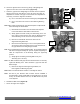
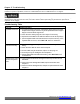
Check the alignment of the Sheaves by placing a Straightedge flat
against
the front face of the PTO Sheave (Figure 31).
5.
Check the gap from the Straightedge to the Belt near the Flywheel
Sheave and near the PTO Sheave. If the gap is the same then no
adjustment is needed. If the gap is not the same then adjustment is
necessary, correct the alignment as follows:
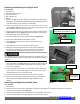
a)
Use a 7/16" Wrench to loosen the Bushing Key Bolt
(Figure 32).
b)
Use a 7/16" Wrench to remove the three Bushing Retaining
Bolts.
Note:
Place a block of wood into the PTO Sheave Spokes to help hold the
belt to loosening the Sheave Bolts.
c)
Reinstall the three Bolts in the Threaded Holes adjacent
to the Holes that the Bolts where removed from.
d)
Slowly tighten the Bolts evenly and alternately (1/4 to 1/2
turn)
until the Sheave pushes away from the Bushing Flange
and the
Bushing can be moved on the Flywheel Shaft.
e)
Remove the three Bolts and reinsert them into the
original Retaining Bolt holes.
f)
Move the Sheave Bushing in or out on the Flywheel Shaft
as needed to take up the difference that you measured for
the gaps between the Straightedge and Belt.
Note:
Prior to retightening the Bushing Retaining Bolts, The un-tightened Sheave
will need to be approximately 1/8" past the original straightedge to
allow
for compression of the Bushing during the tightening
process.
g)
Slowly tighten the Bushing Retaining Bolts evenly and
alternately
(1/4 to 1/2 turn).
Note:
The Bolts should be fairly tight but the Bolt Head does not rest fully
against the Bushing Face. There should be a gap even when the
Bolts are tight.
h)
Recheck the alignment after tightening the Bolts, and
then
retighten the Bushing Key Bolt.
Note: Make sure that the Belt or Sheave is not hitting the Frame.
Note:
The belt on your MIGHTY MAC 3-POINT HITCH CHIPPER is
tensioned with a spring- loaded idler arm and pulley that is set at the
factory. As the Belt stretches
from use, the Belt tension may need
to be adjusted.
6.
Reinstall the Belt Guard (Figure 28).
7.
Secure the Upper TPH Support.
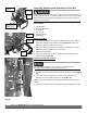
Figure 30
Figure 31
Edge
Gap
PTO
Straight
Edge
Gap
Gap
PTO
Sheave