
Safety & Operating Instructions

3-POINT HITCH
Mighty Mac
Gravity Self-Feeding
CHIPPER
12
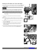
Attaching the 3-POINT HITCH MIGHTY MAC GRAVITY
SELF-FEEDING CHIPPER
Before performing the following procedure, be sure your tractor engine is off,
brake is set, and the key removed for safety.
Figure 10
Figure 11
Figure 12
Upper (pivot)
Draft Arm
Tractor
Hitch Pin
Mounting
Bracket
Note:
The PTO Driveshaft provided with your new machine is sized to fit a
standard
category 1 PTO (1-3/8" DIA. x 6" Spline).
The PTO shaft on the tractor that is to use this machine must
rotate
clockwise when viewing the PTO from the rear of the tractor. If the
PTO rotates
counterclockwise, you must have your tractor modified by
installing a gearbox to
reverse the direction of rotation.
The length of the PTO Driveshaft that is included with your new machine may
need to be modified. See the procedure for checking the PTO Shaft length
needed and
modification instructions in this chapter.
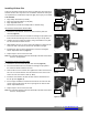
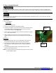
1.
Back the Tractor to the Chipper and position the Lower Draft Arms
near the Chipper Hookup Pins (Figure 10).
2.
Slide the Lower Draft Arms onto the Chipper Hookup Pins and secure
with Tractor Hitch Pins (Figure 11).
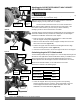
3.
Position the Upper Draft Arm inside the Mounting Bracket and align
with the Mounting Bracket Holes (Figure 12).
4.
Insert the Tractor Hitch Pin to secure the Upper Draft Arm to the Chipper.
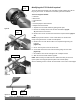
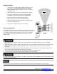
Calculating length of PTO Shaft needed
The PTO Shaft provided with your Chipper is 27" overall compressed length and
will work for most applications without modifications. Before you install the PTO
Shaft it is good practice to run through the following dimension checks to
calculate optimum PTO Shaft length to determine if modifications are needed.
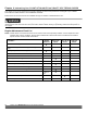
Without the PTO Shaft installed, use the table below to record the
dimensions as outlined in the following steps.
SHAFT TO SHAFT MEASUREMENTS
ON GROUND
Inches
SHAFTS LEVEL
Inches
FULLY RAISED
Inches
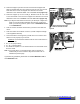
1.
Lower the Chipper all the way onto the ground in the operating
position. Measure from the end of the Tractor PTO Shaft to the end
of the Chipper PTO Shaft and record this dimension in the “ON
GROUND” row of the table above (Figure 13).
Figure 13
Arm
Draft Arms
Shaft
Chipper
Mounting Hole
Upper (pivot) Draft
Arm
Lower (lifting)
Draft Arms
Chipper
Hookup
Pins
Tractor
Hitch Pin
Upper (pivot)
Draft Arm
Mounting
Bracket
Tractor
Hitch Pin
Chipper
Mounting Hole
End of
Chipper PTO
Shaft
Chipper on the
Ground