
Technical information

Technical Information
97
G 600/G 800
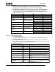
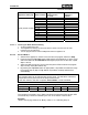
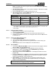
Program selector switch
position (o’clock)
Fault registered Fault indication
1 F0 No fault registered
--
2 F1
NTC sensor or connections
open-circuited
All program sequence
LEDs flash
3 F2
NTC sensor or connections
short-circuited
All program sequence
LEDs flash
4 F3 Pulse failure
All program sequence
LEDs flash
5 F4 Heating fault
All program sequence
LEDs flash
6 F5
Drainage fault -heater
pressure switch
“Intake/Drain” LED flashes
7 F6
Water intake fault - too few
pulses at start of step
“Intake/Drain” LED flashes
8 F7
Water intake fault - too few
pulses at end of step
“Intake/Drain” LED flashes
9 F8
Water intake fault - heater
pressure switch
“Intake/Drain” LED flashes
Table 6-24: G 680, G 880 Fault Codes
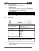
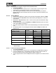
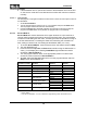
6.8.4.3.2 Program Index
1. Access Service Mode 2.
2. Turn the program selector switch to the 2 o'clock position. The Top solo LED flashes.
3. Press the Top solo button.
4. The Top solo LED lights up when the selector switch is turned to the position where the
program index is registered. See Table 6-25.
Program selector switch
position (o’clock)
Program index
Electronic version
1 IP0 Start of series EPLZ 501
2 P1 Start of series EPLZ 501
3 P2 With update feature EPLZ 501
4 P3 New electronic EPLZ 520
5 P4 - -
6 P5 New water path EPLZ 520
7 - etc. -
Table 6-25: G 680, G 880 Program Indices
6.8.4.3.3 Setting the Flow Meter
1. Access Service Mode 2.
2. Turn the program selector switch to the 4 o'clock position. The Top solo LED flashes.
3. Press the Top solo button. Turn the program selector switch to the 6 o'clock position and
press Top solo again.
4. To save the option: Turn the program selector switch to Stop and switch the appliance off.
6.8.4.4 Other Fault Indications
6.8.4.4.1 Program Interruption and All Program Sequence LEDs Flash
Program selection is not possible.
The electronic has registered a fault during program operation. This can be checked via
Service Mode 2.