
Technical information

Technical Information
30
G 600/G 800
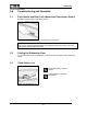
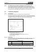
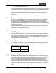
Figure 4-5: Filter Assembly
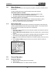
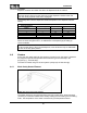
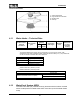
4.11 Water Intake – Technical Data
Solenoid valve
electrical
connection
Flow pressure
(psi)
Flow rate
(gal/min)
Connection
lead length
1
Threaded
union
Cutout
dimensions
for valve
assembly
housing
60cm
model
45cm
model
120VAC (60Hz) 14.5 - 145 1.3 1.1 5 feet (1.5m) ¾” hose 2” x 4”
Table 4-5: WaterProof System Data
1
The standard WaterProof system can be exchanged for a 15-foot (4.5m) version. With
dishwashers from index 24 (additional seal under both solenoid valves), a 5’ (1.5m) metal hose
can be connected to the WPS valve as an extension.
Restrictor color Flow rate
Green
1.1 gal/min (4.1L/min)1
Gray
1.3 gal/min (4.9L/min)2
White 1.4 gal/min (5.25L/min)
Blue 1.6 gal/min (6.0L/min)
Table 4-6: Flow Restrictor Data
1
Standard with 45cm (Slimline) models
2
Standard with 60cm (full-size) models
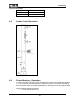
Water Inlet Mixer
Wash water hardness solenoid valve (Y5)
120VAC 60Hz
Softener reactivation reservoir capacity
13.5 fl.oz. (400mL) for 60cm model
11.5 fl.oz. (340mL) for 45cm model
Flow meter Approx. 200-220 pulses/liter
Table 4-7: Water Inlet Mixer Data
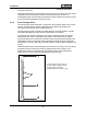
4.12 WaterProof System (WPS)
The water inlet valve (Y2) consists of two (2) electromechanical valves mounted
within a waterproof box located at the water connection (end of the water intake
hose).
1 Coarse filter/handle
2 Large surface area fine filter
3 Microfine filter
4 Filter cap