Operating and installation instructions SmartLine downdraft extractor To prevent the risk of accidents or damage to the appliance, it is essential to read these instructions before it is installed and used for the first time. en-AU, NZ M.-Nr.
Contents Warning and Safety instructions...................................................................... 4 Caring for the environment .............................................................................. 14 Overview............................................................................................................. Downdraft extractor............................................................................................. Controls / Indicators....................................
Contents Flush-fit ............................................................................................................... Installation notes – flush-fit ................................................................................. Worktop cut-out – flush-fit .................................................................................. Spacer bars – flush-fit ......................................................................................... Installation dimensions – Flush ...........
Warning and Safety instructions This downdraft extractor complies with all relevant safety requirements. However, inappropriate use can lead to personal injury and damage to property. Please read these operating and installation instructions carefully before using the downdraft extractor for the first time. They contain important information on safety, installation, use and maintenance of the appliance. This prevents both personal injury and damage to the downdraft extractor.
Warning and Safety instructions Correct application This downdraft extractor is designed for domestic use and for use in similar environments by guests in hotel or motel rooms, bed & breakfasts and other typical living quarters. This does not include common/shared facilities or commercial facilities within hotels, motels or bed & breakfasts. The downdraft extractor is not suitable for outdoor use. The downdraft extractor must only be used to extract vapours and remove odours from cooking.
Warning and Safety instructions Safety with children Young children must be kept away from the downdraft extractor. Older children may only use the downdraft extractor without supervision if they have been shown how to use it in a safe manner. They must be aware of the potential dangers caused by incorrect operation. Cleaning work may only be carried out by older children under the supervision of an adult.
Warning and Safety instructions Technical safety Unauthorised installation, maintenance and repairs (including removal of any cover) can cause considerable danger for the user. Installation, maintenance and repairs must only be carried out by a Miele authorised technician. The downdraft extractor must only be installed and operated in combination with those SmartLine appliances and cooktops specified by Miele. A damaged appliance is dangerous. Check it for any visible damage.
Warning and Safety instructions For safety reasons, this downdraft extractor may only be used after it has been built in. This downdraft extractor must not be installed and operated in mobile installations (e.g. on a ship). Touching or tampering with electrical connections or components and mechanical parts is highly dangerous to the user and can cause operational faults. Only open the housing as described in the installation instructions and in the Cleaning and care section of this booklet.
Warning and Safety instructions During installation, maintenance and repair work, the downdraft extractor must be completely disconnected from the mains electricity supply. It is only completely isolated from the electricity supply when: - the mains circuit breaker is switched off, or - the screw-out fuse is removed (in countries where this is applicable), or - it is switched off at the wall socket and the plug is withdrawn from the socket.
Warning and Safety instructions Using at the same time as other heating appliances that depend on the air from the room Warning - danger of toxic fumes! Great care should be taken when using the downdraft extractor at the same time and in the same room or area of the house as another heating appliance which depends on the air in the room.
Warning and Safety instructions In order to ensure safe operation, and to prevent gases given off by the heating appliances from being drawn back into the room when the downdraft extractor and the heater are in operation simultaneously, an underpressure in the room of 0.04 mbar (4 pa) is the maximum permissible.
Warning and Safety instructions Correct use Open flames are a fire hazard! Never use an open flame beside the downdraft extractor. To avoid the danger of fire, do not flambé or grill over an open flame. When switched on, the downdraft extractor could draw flames into the filter. Kitchen grease deposits could ignite. Overheated oil and fat can ignite, causing fire damage to the downdraft extractor. When cooking with oil or fat, chip pans and deep fat fryers etc., do not leave the pans unattended.
Warning and Safety instructions Cleaning and care The steam from a steam cleaning appliance could reach electrical components and cause a short circuit. Do not use a steam cleaner to clean the downdraft extractor. There is a risk of fire if cleaning is not carried out as described in these operating instructions. Accessories Use only genuine original Miele spare parts.
Caring for the environment Disposal of the packing material Disposing of your old appliance The transport and protective packaging has been selected from materials which are environmentally friendly for disposal, and can normally be recycled. Electrical and electronic appliances often contain valuable materials. They also contain specific materials, compounds and components, which were essential for their correct function and safety.
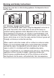
Overview Downdraft extractor a Extraction grille b Grease filter c Cover with control unit d Casing e Moisture collection tray f Air duct g Fan h E-box 15
Overview Controls / Indicators a For switching the downdraft extractor on/off b Numerical keybank for setting the power level 16
Overview Accessories supplied Extraction grille The accessories supplied with your appliance, as well as a range of optional ones, are available to order from Miele (see “Optional accessories”).
Cleaning the SmartLine appliance for the first time Please stick the extra data plate for the appliance supplied with this documentation in the space provided in the “Service” section of this booklet. Alternatively, the additional label can be stuck near the appliance if the appliance markings are not visible after installation. Remove any protective wrapping and stickers (except the data plate). Clean the ceramic surface with a damp cloth, and then wipe dry.
Description of the functions Depending on the model of the downdraft extractor, the following options are available: Air extraction mode The air is drawn in and cleaned by the grease filter and directed outside. Recirculation mode (DUU 1000(-1) conversion kit required) The air is drawn in and cleaned by the grease filter. The air is then directed into the recirculation box where it is also cleaned by the charcoal filter. The cleaned air is then recirculated back into the kitchen.
Tips on saving energy This downdraft extractor operates very efficiently and economically. The following will help you to save even more energy when using it: - It is important to ensure that the kitchen is well ventilated during operation. In extraction mode if there is insufficient air flow, the downdraft extractor cannot operate efficiently and this causes increased operating noise levels. - Always cook with the lowest possible cooking setting.
Operation Switching the downdraft extractor on Switching the downdraft extractor off Touch the sensor. The sensor controls go out. If the downdraft extractor is not switched off, it will switch itself off 12 hours after the last automatic operation. Insert the extraction grille. Run-on time Touch the sensor. In order to rid kitchen air of steam and odours, the downdraft extractor continues to run for 5 minutes on the power level that was set last.
Cleaning and care Risk of burning due to hot surfaces. The surfaces will be hot after use. Switch the downdraft extractor and the cooking elements off. Allow the surfaces to cool down before cleaning the downdraft extractor. Allow the SmartLine appliance to cool down before cleaning. Clean the SmartLine appliance and accessories after each use. Dry the SmartLine appliance thoroughly every time after cleaning to avoid limescale residue.
Cleaning and care Ceramic surface Risk of damage by pointed objects. The seal between the SmartLine element and the worktop could suffer damage. Do not use pointed objects for cleaning. Do not use washing-up liquid to clean the appliance. Using washingup liquid will not remove all soiling and residues. An invisible film can develop that can lead to discolouration of the ceramic glass. This discolouration cannot be removed.
Cleaning and care Grease filter / Extraction grille The extraction grille and the reusable metal grease filter in the downdraft extractor collect solid matter from kitchen vapours (grease, dust, etc.) and therefore prevent soiling of the downdraft extractor. Accumulated grease solidifies over a longer period of time and makes cleaning more difficult. The grease filter should therefore be cleaned at least every 3 to 4 weeks. Risk of fire due to soiled grease filter.
Cleaning and care Interior of the casing When removing the grease filter for cleaning, also clean off any accessible oil or fat build-up from the casing. Doing so will prevent a fire hazard.
Problem solving guide With the help of the following guide, minor faults in the performance of the appliance, some of which may result from incorrect operation, can be remedied without contacting Miele. This will save you time and money because you won't need a service call. Please note that a call-out charge will be applied to unnecessary service visits where the problem could have been rectified as described in these operating instructions.
Optional accessories Miele offers a range of useful accessories, as well as cleaning and conditioning products for your appliance. FlameGuard These products can be ordered from the Miele online shop. They can also be ordered directly from Miele (see end of this booklet for contact details). For fitting in place between the downdraft extractor and a gas cooking appliance. Original Miele ceramic and stainless steel cleaner 250 ml Removes heavy soiling, limescale deposits and aluminium residues.
Service Contact in case of fault In the event of any faults which you cannot remedy yourself, please contact Miele. You can book a Miele customer service call-out online at www.miele.com/ service. Contact information for Miele can be found at the end of this booklet. Please quote the model and serial number of your appliance when contacting Miele. This information can be found on the data plate. Data plate Adhere the extra data plate supplied with the appliance in the space below.
*INSTALLATION* Installation Safety instructions for installation Risk of damage from incorrect installation. Incorrect installation can cause damage to the SmartLine appliance. The SmartLine appliance must only be installed by a suitably qualified and competent person. Damage from falling objects. Take care not to damage the SmartLine appliance when fitting wall units above it. Fit the wall units before the SmartLine appliance.
*INSTALLATION* Installation Installation examples Recirculation mode Air extraction mode 30
*INSTALLATION* Installation Surface-mounted Tiled worktop Installation notes – surface-mounted Sealing between the SmartLine appliance and the worktop The SmartLine appliance and worktop may be damaged if the appliance needs to be removed after it has been sealed with a sealant. Do not use any sealant between the SmartLine appliance and the worktop. The sealing strip under the edge of the top part of the appliance provides a sufficient seal for the worktop.
*INSTALLATION* Installation Installing several SmartLine appliances The gaps between the individual SmartLine appliances must be sealed with a silicone sealant that is heatresistant to at least 160 °C. With flushfit installation, the gap between the SmartLine appliance(s) and the worktop must also be sealed with a silicone sealant that is heat-resistant to at least 160 °C.
*INSTALLATION* Installation Worktop cut-out – surface-mounted 500 + 1 B ßR 4 010 10 B Information for calculating the cut-out The appliances overlap the worktop by 10 mm. When installing several appliances, a distance of 2 mm must be observed between the individual appliances.
*INSTALLATION* Installation Installation with a downdraft extractor Sample combinations 34 Number x width [mm] Dimension B [mm] Cooking appliances Downdraft extractor 1 x 378 1 x 120 480 2 x 378 1 x 120 860 1 x 378 1 x 620 2 x 120 1224 3 x 378 2 x 120 1362 2 x 378 1 x 620 2 x 120 1604 4 x 378 2 x 120 1742 1 x 620 2 x 120 844 +1 +1 +1 +1 +1 +1 +1
*INSTALLATION* Installation Installation without a downdraft extractor Sample combinations Number x width [mm] Cooking appliances Dimension B [mm] +1 1 x 378 358 2 x 378 738 1 x 378 1 x 620 980 3 x 378 1118 2 x 378 1 x 620 1360 4 x 378 1498 +1 +1 +1 +1 +1 35
*INSTALLATION* Installation Spacer bars – surface-mounted When installing several SmartLine appliances, an additional spacer bar must be fitted in between the individual appliances. The clips supplied with the spacer bars are only required for installing a CSDA 700x FL.
*INSTALLATION* Installation Installation dimensions – Surface-mounted All dimensions in this instruction booklet are given in mm.
*INSTALLATION* Installation Air duct dimensions – surface-mounted – worktop depth 600 mm Side view a For maintenance work, it must be possible to remove the rear cabinet wall. The cabinet wall and an adjoining room wall or a piece of furniture must be at least 110 mm apart to ensure sufficient room for the exhaust ducting. b After installation, the removable moisture collection tray must be accessible from below. Two quick-release catches have to be opened to remove the tray.
*INSTALLATION* Installation Front view View from above 39
*INSTALLATION* Installation Air duct dimensions – surface-mounted – worktop depth greater than 600 mm View from the side – right air duct connection a For maintenance work, it must be possible to remove the rear cabinet wall. The cabinet wall and an adjoining room wall or a piece of furniture must be at least 110 mm apart to ensure sufficient room for the exhaust ducting. b Variable length of middle section c After installation, the removable moisture collection tray must be accessible from below.
*INSTALLATION* Installation View from the front – right air duct connection View from above – right air duct connection 41
*INSTALLATION* Installation If you want to install the air duct to the left of the downdraft extractor, the worktop must be at least 665 mm deep.
*INSTALLATION* Installation Installation – surface-mounted Wooden worktops If the worktop is more than 24 mm deep, it must be cut out underneath on the building-in side on the right or left-hand side. Fit the bracket so that it sits flush with the top edge of the worktop cutout. a Worktop b Maximum 24 mm c 12 mm Secure the bracket with the 3.5 x 25 mm wood screws supplied. Granite and marble worktops You will need heavy-duty doublesided tape (not supplied) to secure the bracket.
*INSTALLATION* Installation Preparing the worktop Wooden worktops Create the worktop cut-out. Remember to maintain the minimum safety distances (see "Installation – Safety distances"). Seal the cut surfaces of wooden worktops with a suitable sealant to avoid swelling caused by moisture. The sealant must be heat-resistant. Make sure the sealant does not come into contact with the top surface of the worktop.
*INSTALLATION* Installation Installing the downdraft extractor The downdraft extractor can be installed with the connector for the air duct on either the right or the left-hand side. Remove the drip tray from the casing. a Connector for air duct on the right b Connector for air duct on the left Stick the supplied sealing strip under the edge of the cover. Do not apply the sealing strip under tension. Fit the clips onto the spacer bars. Guide the control cable downwards between the spacer bars.
*INSTALLATION* Installation E-box Connection to window contact, if required The window contact is a Mains connection cable b Connection to window contact c Connection socket for the fan power cable d Connection socket for the fan control cable e Connection socket for the control unit cable 46 connected to the mains voltage. Danger of electric shock! Disconnect the downdraft extractor from the mains electricity supply before connecting the switching system.
*INSTALLATION* Installation Loosen the lug and pull the plug out. Connecting the e-box Connect the fan power cable and fan control cable to the e-box and the fan. Connect the control unit cable to the e-box. The socket positions are designed in such a way that they cannot be mixed up. Loosen the strain relief screw and unlock the casing on both sides . Open the casing. Remove the stopper. Connect the downdraft extractor to the mains electricity supply.
*INSTALLATION* Installation Flush-fit Installation notes – flush-fit Flush-fit installation is only possible in natural stone (granite, marble), solid wood and tiled worktops. For installation in worktops made of other materials, please consult the relevant manufacturer as to whether their worktops are suitable for flush-fit installation.
*INSTALLATION* Installation Installing several SmartLine appliances The gaps between the individual SmartLine appliances must be sealed with a silicone sealant that is heatresistant to at least 160 °C. With flushfit installation, the gap between the SmartLine appliance(s) and the worktop must also be sealed with a silicone sealant that is heat-resistant to at least 160 °C.
*INSTALLATION* Installation Worktop cut-out – flush-fit 500 + 1 524 +1 A B ßR4 5,5 +0,5 * 5,5 +0,5 * 02 0 10 0 10 02 12 12 B A Natural stone worktop B A Wooden worktop * 7+0.5 mm with CS 7611 FL Information for calculating the cut-out The appliances overlap the stepped cut-out by 10 mm. When installing several appliances, a distance of 2 mm must be observed between the individual appliances.
*INSTALLATION* Installation Installation with a downdraft extractor Number x width [mm] Sample combinations Cooking appliances Downdraft Dimension A Dimension B [mm] [mm] extractor +1 480 +1 860 1 x 378 1 x 120 504 2 x 378 1 x 120 884 1 x 378 1 x 620 2 x 120 1248 3 x 378 2 x 120 1386 2 x 378 1 x 620 2 x 120 1628 4 x 378 2 x 120 1766 1 x 620 2 x 120 868 +1 +1 +1 1224 +1 1362 +1 1604 +1 1742 +1 +1 +1 +1 +1 +1 844 51
*INSTALLATION* Installation Installation without a downdraft extractor Sample combinations Number x width [mm] Dimension A [mm] Dimension B [mm] Cooking appliances 52 +1 358 +1 738 1 x 378 382 2 x 378 762 1 x 378 1 x 620 1004 3 x 378 1142 2 x 378 1 x 620 1384 4 x 378 1522 +1 +1 +1 980 +1 +1 1118 +1 1360 +1 1498 +1 +1 +1
*INSTALLATION* Installation Spacer bars – flush-fit When installing several SmartLine appliances, an additional spacer bar must be fitted in between the individual appliances. The clips supplied with the spacer bars are only required for installing a CSDA 700x FL.
*INSTALLATION* Installation Installation dimensions – Flush All dimensions in this instruction booklet are given in mm.
*INSTALLATION* Installation Air duct dimensions – flush-fit – worktop depth 600 mm Side view a For maintenance work, it must be possible to remove the rear cabinet wall. The cabinet wall and an adjoining room wall or a piece of furniture must be at least 110 mm apart to ensure sufficient room for the exhaust ducting. b After installation, the removable moisture collection tray must be accessible from below. Two quick-release catches have to be opened to remove the tray.
*INSTALLATION* Installation Front view View from above 56
*INSTALLATION* Installation Air duct dimensions – flush-fit – worktop depth greater than 600 mm View from the side – right air duct connection a For maintenance work, it must be possible to remove the rear cabinet wall. The cabinet wall and an adjoining room wall or a piece of furniture must be at least 110 mm apart to ensure sufficient room for the exhaust ducting. b Variable length of middle section c After installation, the removable moisture collection tray must be accessible from below.
*INSTALLATION* Installation View from the front – right air duct connection View from above – right air duct connection 58
*INSTALLATION* Installation If you want to install the air duct to the left of the downdraft extractor, the worktop must be at least 665 mm deep.
*INSTALLATION* Installation Installation – flush-fit Wooden worktops If the worktop is more than 28 mm deep, it must be cut out underneath on the building-in side on the right or left-hand side. Fit the bracket so that it sits flush with the top edge of the lower step of the stepped cut-out. a Worktop b Maximum 24 mm c 12 mm Secure the bracket with the 3.5 x 25 mm wood screws supplied. Granite and marble worktops You will need heavy-duty doublesided tape (not supplied) to secure the bracket.
*INSTALLATION* Installation Preparing the worktop Wooden worktops Create the worktop cut-out. Remember to maintain the minimum safety distances (see "Installation – Safety distances"). Seal the cut surfaces of wooden worktops with a suitable sealant to avoid swelling caused by moisture. The sealant must be heat-resistant. Make sure the sealant does not come into contact with the top surface of the worktop. For wooden worktops, secure the wooden frames 5.5 mm below the upper edge of the worktop.
*INSTALLATION* Installation Installing the downdraft extractor The downdraft extractor can be installed with the connector for the air duct on either the right or the left-hand side. Remove the drip tray from the casing. a Connector for air duct on the right b Connector for air duct on the left Stick the supplied sealing strip under the edge of the cover. Do not apply the sealing strip under tension. Fit the clips onto the spacer bars. Guide the control cable downwards between the spacer bars.
*INSTALLATION* Installation E-box Connection to window contact, if required The window contact is a Mains connection cable b Connection to window contact c Connection socket for the fan power cable d Connection socket for the fan control cable e Connection socket for the control unit cable connected to the mains voltage. Danger of electric shock! Disconnect the downdraft extractor from the mains electricity supply before connecting the switching system.
*INSTALLATION* Installation Loosen the lug and pull the plug out. Connecting the e-box Connect the fan power cable and fan control cable to the e-box and the fan. Connect the control unit cable to the e-box. The socket positions are designed in such a way that they cannot be mixed up. Loosen the strain relief screw and unlock the casing on both sides . Open the casing. Remove the stopper. Connect the downdraft extractor to the mains electricity supply.
*INSTALLATION* Installation Exhaust ducting Before installation, it is important to read the following information. This is particularly crucial when using the downdraft extractor at the same time as a heating appliance that relies on oxygen from the same room, which could result in the buildup of toxic fumes. It is particularly important that the “Warning and Safety instructions” are observed. The downdraft extractor should be installed according to local and national building regulations.
*INSTALLATION* Installation If the exhaust air is to be ducted into a flue, the ducting must be directed in the flow direction of the flue. If ducting is to be laid horizontally, it must be laid with a downwards sloping gradient. This is to ensure that condensate cannot drain back into the extractor. If the vent ducting is to run through rooms, ceiling space, etc. there may be great variations in temperature between the different areas. The problem of condensation will need to be addressed.
*INSTALLATION* Installation Electrical connection Total power output We recommend that you connect the SmartLine appliance to the mains via a suitable switched electrical socket. This simplifies servicing. The socket must be easily accessible after the SmartLine appliance has been installed. See data plate. Danger of injury! Installation, repairs and other work by unqualified persons could be dangerous. Miele cannot be held liable for unauthorised work.
*INSTALLATION* Installation Replacing the mains connection cable Danger of electric shock! Incorrect connection to the electricity supply may result in an electric shock. The mains connection cable must only be replaced in accordance with current local and national safety regulations. When replacing the mains connection cable, it must be replaced with cable type H 05 VV-F by a Miele authorised service technician or a suitably qualified and competent electrician in order to avoid a hazard.
Miele Australia Pty. Ltd.
CSDA 7001 FL en-AU, NZ M.-Nr.