
Specifications


VIDEO TROUBLESHOOTlNG
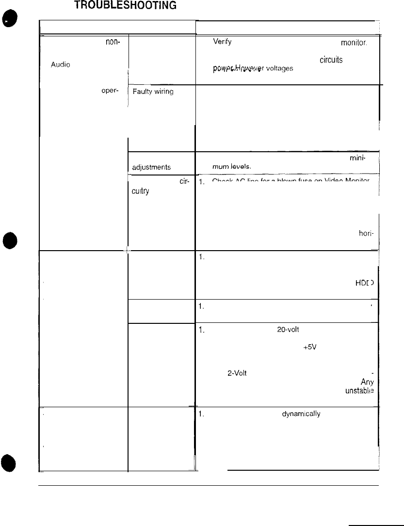
Symptom
1 Cause
l Monitor appears non- Power problem
functional
l
.Audio
is present ,
l Video Game Machine
(VGM) controls oper-
ate normally
l Graphic images from
game do not appear
l No audio
l Power-up self-test
runs
l White areas at screen
edges appear tinged
with color
l Dots at screen edges
appear ovoid or cylin-
drical
t
c
Improper monitor
adlustments
Faulty monitor
cir-
cultiy
Improper compo-
nents
Hard Disk Drive
(HDD) problems
Power Problems
Picture tube
dynamic conver-
gence is out Of
alignment
Required Action
1. Verrfy
connection of AC Power to video
monrtor.
Inspect neck of CRT in dim light. Glowing filament
near CRT base confirms monitor
circurts
receive
nn~~r Hnwavnr
voltages
or signals may not be
r”
II
_.,
._
-.
_
,
normal.
1.
Switch off power. Verify that video signal and
Remote Adjustment Board connectors seat prop-
erly on Video Monitor Board.
2.
Assure that video cables connect to circuit boards
and Arcade Computer.
3. Assure that no wires are caught on chassis or
mounting brackets.
1.
Try setting Brightness and Contrast above mini-
1.
Check AC line for a blown fuse on Video Monitor
Board. Replacement fuses must be identically
rated.
2.
If the fuse is good, verify video monitor operates
correctly by placing it in a working VGM.
3.
If monitor is bad; Check monitor power supply.
4.
If the power supply is good, Check monitor bon
zontal output transistor and related circuitry.
I. Verify circuit boards are correct for this game.
Labels on each board record manufacturers’
name, assembly number and hardware version.
2.
Verify HDD is correct for this game. Label on
HDC
records assembly number and software version.
1.
Allow game to load normally. Note and record any
error messages that occur during self-test.
1.
Turn on Power. Use 20-volt DC setting on digital
voltmeter to measure DC voltages present at
Power connector pins. Verify +5V source if it is
adjustable. Refer to Cabinet Wiring Diagram for
specific wiring information and voltage limits.
2.
Use Z-Volt AC setting on digital voltmeter to mea
sure DC voltages at Power Connector pins. An:
reading indicates the supply voltages are
unstable
and may contain ripple or noise.
1.
Have service bureau dynamrcally re-converge
monitor. This procedure requires removing and
repositioning yoke. Service bureau must follow
instructions from monitor manufacturer.
ARCTIC THUNDER
TROUBLESHOOTING 9